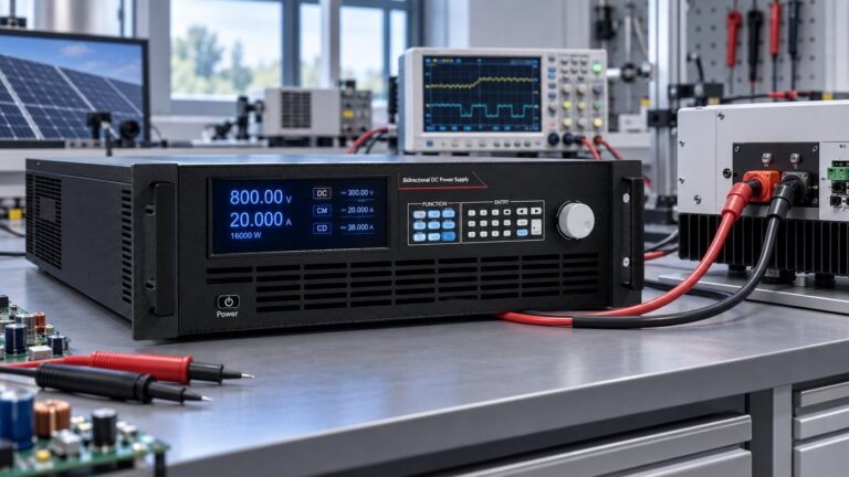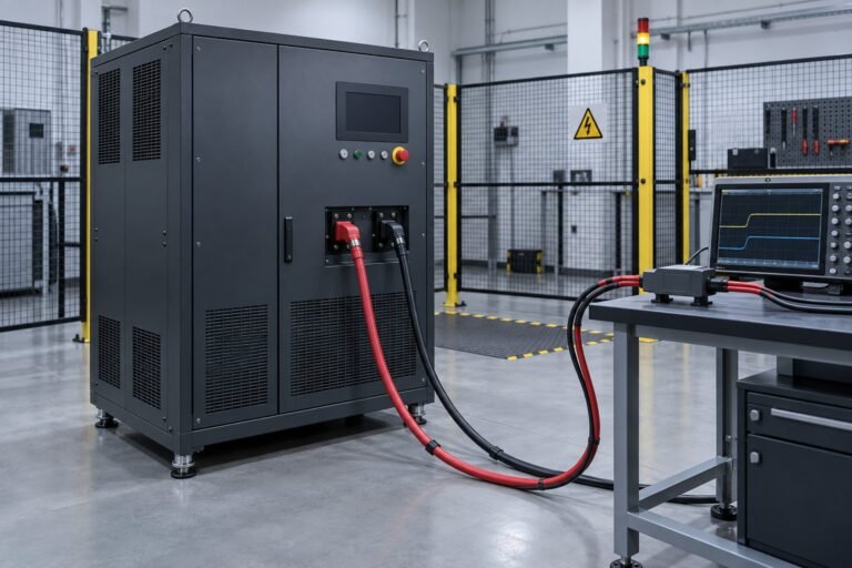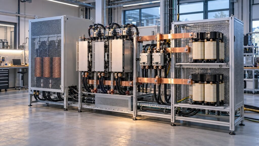
AC to DC converter regeneration is commissioned by proving the DC bus is precharged before grid connection, then validating LCL damping under a defined grid impedance. You should record contactor timing, DC-link voltage, power factor, input-current THD, returned kW and measured efficiency at your chosen 360 V, 750 V, 1500 V or 2250 V class.
This guide focuses on the AC-to-DC grid interface. The March 2026 Bi-Directional Active Front End Reference Design reports a 22 kW SiC, six-switch, two-level AFE with an adjustable DC bus, 98.5% peak efficiency and 4.6 kW/L power density. The IIT Madras study shows why filter damping changes the buyer trade-off at 22–350 kW.
What must you check before applying AC input?
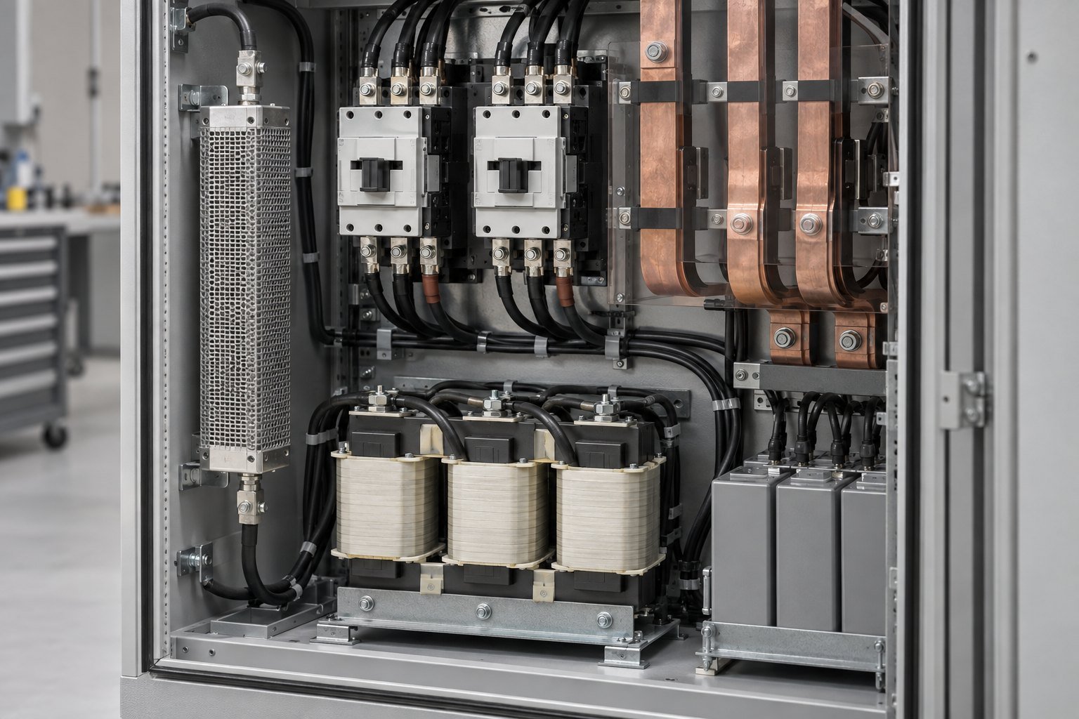
Before AC input, verify the bus threshold, phase sequence, isolation state and precharge path. The imperix Active Front End (AFE) guidance requires Vdc ≥ VLL,peak before grid connection. At a 400 V line-to-line RMS supply, VLL,peak is approximately 566 V. Connecting below that value can turn the anti-parallel diodes into an uncontrolled inrush path.
Your interlock should keep gate pulses inhibited while the AC contactor is open and the DC link is below its connection threshold. Measure the precharge current, bus rise time and resistor temperature. A contactor that closes early can weld, trip the input protection or stress the SiC switches before current control is active.
- Record the incoming voltage as 400 V line-to-line RMS and confirm phase rotation before energisation.
- Confirm the DC link is below 50 V before service access and that the discharge circuit operates after shutdown.
- Verify the precharge resistor is pulse-rated for the calculated capacitor energy and initial current.
- Set the grid-connection threshold above 566 V for this 400 V supply, then verify the threshold in the controller log.
See also: High Voltage DC Power Supply Selection Guide
How do you sequence an ac to dc converter regeneration start?
Use a three-stage start: isolate the hardware, precharge the DC link, then connect the grid and ramp current. Keep the first power command at zero. The sequence below gives you a repeatable 750 V-class commissioning baseline.
- Verify protective earth, phase order and the 400 V line-to-line supply. Abort if phase error exceeds 2° or the phase sequence is incorrect. Failure mode: the PLL locks to the wrong sequence and the current controller drives the wrong phase.
- Close the precharge contactor through a 100 Ω pulse-rated resistor. At 750 V, the initial resistor current is 7.5 A if the bus starts at 0 V. Failure mode: a bypassed or shorted resistor produces an uncontrolled capacitor inrush.
- Wait until Vdc reaches at least 600 V, then hold that level for 100 ms before closing the main AC contactor. Failure mode: closing below the 566 V line-voltage peak allows anti-parallel diode conduction and destructive inrush.
- Open the precharge contactor within 50 ms of the main contactor closing. Confirm the bus remains stable and DC ripple stays below 2% peak-to-peak at no load. Failure mode: a delayed bypass leaves the resistor carrying continuous power.
- Enable PLL and dq-axis current control at 0 A, then ramp the command by 1 kW/s. Failure mode: a rapid current step excites the LCL resonance before damping has been verified.
- Repeat the ramp at a defined grid impedance. At 6% equivalent impedance at the point of common coupling, stop if current oscillation persists above 5% RMS or input-current THD exceeds 5%.
See also: DC Power Supply Ripple Measurement: 360–2250 V
How should you damp the LCL filter for grid return?
An LCL filter reduces switching ripple but introduces a resonance that must be controlled. RC damping is practical when low THD and simple control are priorities. The IIT Madras May 2026 seminar reports that the resistor can dissipate significant power at 22–350 kW, creating thermal stress and requiring a bulky resistor and heat sink.
The same IIT Madras work compares R, RC, RLC and capacitor current feedback under identical LCL parameters. It uses dq-axis current control, PLL synchronisation and Typhoon HIL validation. Specify the damping method with its loss, thermal rise, control delay and stability evidence. Do not accept a low THD result without recording the test impedance.
| Damping choice | What you should verify | Use when |
|---|---|---|
| R | Resistor loss, temperature rise and resonance suppression | You need a simple passive baseline |
| RC | THD, resistor dissipation and heat-sink temperature at 22–350 kW | Low THD matters more than passive-loss minimisation |
| RLC | Stability, component tolerance and behaviour across grid impedance | You can validate the network over several operating points |
| Capacitor current feedback | Sensor bandwidth, control delay and HIL stability | You can manage added control and measurement complexity |
Use 6% equivalent grid impedance as a defined stress point for your 750 V acceptance test. This is a test condition, not a universal resonance value. If the current waveform develops sustained oscillation at that impedance, reduce the power command, inhibit grid return and correct the damping or control settings before continuing.
What should a 750 V acceptance test record?
For a 750 V class, run a 10.0 kW grid-return test from a 400 V three-phase input. Use the following sequence as an acceptance template. The 98.5% peak figure in the reference design is a benchmark, not a substitute for your measured result.
| Checkpoint | Test action | Pass condition or failure trigger |
|---|---|---|
| Precharge resistor | Measure the installed 100 Ω path and initial current | 7.5 A maximum at 750 V; fail for a bypassed, open or thermally overloaded resistor |
| Contactor timing | Timestamp Kpre, Vdc threshold, Kac and Kpre opening | Kac closes only after Vdc ≥ 600 V for 100 ms; Kpre opens within 50 ms |
| DC-link threshold | Apply 400 V line-to-line RMS and monitor Vdc | At least 600 V before grid connection; fail if Kac closes below 566 V |
| Power factor | Return 10.0 kW with the power analyser at the AC input | PF ≥ 0.99 at steady state |
| Input-current THD | Measure harmonic groups using IEC 61000-4-7 Clause 5 | THD ≤ 5%; report the edition, bandwidth and grid impedance |
| Returned power | Command 10.0 kW from the 750 V DC bus and measure grid-side power | At least 9.70 kW returned to the grid; record the signed value |
| Measured efficiency | Calculate returned grid power divided by absorbed DC power | At least 97.0% at the 10.0 kW test point |
| LCL stress | Repeat the test at 6% equivalent grid impedance | Current oscillation below 5% RMS; fail on sustained resonance or THD above 5% |
AMTech Drives’ Active Front-End Converter | Regenerative Power Quality Solution is a useful description of the grid-facing role. Your acceptance record should make that claim measurable: PF, THD, returned kW, bus stability and efficiency must all be captured at the same operating point.
What do engineers ask about regenerative AC-DC conversion?
What does active front end converter mean in this test?
Here, an active front end converter is the controlled six-switch, two-level AC interface. You judge it by current quality, stable power flow and protection timing, not by topology alone.
What is regenerative AC-DC conversion?
Regenerative AC-DC conversion sends energy from the DC test item back through the controlled AC interface. The returned kW and measured efficiency must be recorded at the grid connection point.
What is a four-quadrant rectifier?
A four-quadrant rectifier controls signed voltage and current so the converter can source or absorb power. For commissioning, verify each commanded direction through measured current, voltage and grid power.
What does rückspeisefähige DC-Last and bidirektionale DC-Stromversorgungen mean?
A rückspeisefähige DC-Last is a regenerative DC load that returns absorbed energy to the AC grid. Bidirektionale DC-Stromversorgungen are bidirectional DC power supplies that source and sink energy under controlled voltage and current limits.
How should you specify the production test?
Specify the DC class, AC voltage, precharge resistor, contactor delays, grid impedance, PF limit, THD limit, returned kW and efficiency calculation before the hardware arrives. For a 360 V, 750 V, 1500 V or 2250 V system, review our bidirectional and regenerative DC power supply range, then request a quote for your measured acceptance sequence →