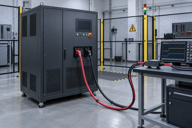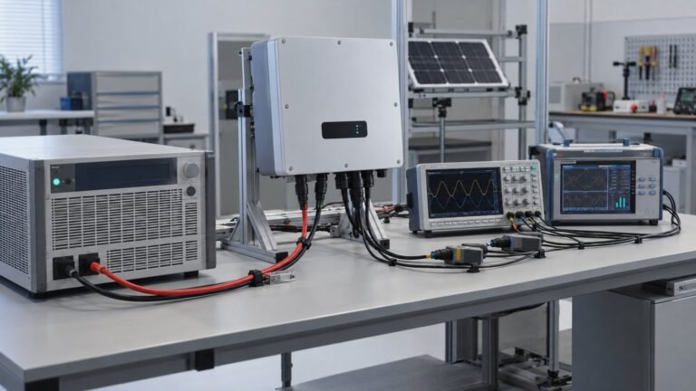
For IEC 62109-2 2026, change your PV inverter safety testing plan to include controlled full-load-to-zero and zero-to-full load steps. Repeat each direction three times, sample instantaneous voltage at no less than 10 kHz, and retain one annotated 1,500 V waveform with trigger, overshoot, recovery and pass/fail evidence.
I’m Ashkan, power supply engineer at Ultra Power Systems. The practical task is turning the revised safety requirements into a repeatable bench method while the 2026 edition moves from pre-release status towards publication.
What do the IEC 62109-2 2026 changes require?
The IEC 62109-2:2026 PRV | IEC page says the second edition replaces IEC 62109-2:2011. It applies to equipment up to 1,500 V DC and 1,000 V AC, adds AC source-management testing, changes transient-output requirements and removes allowances for intentionally non-sinusoidal waveforms.
| Revision point | Bench consequence | Planning action |
|---|---|---|
| Second edition | Your legacy evidence needs a revision review | Map old records against the new clauses |
| 1,500 V DC and 1,000 V AC scope | The maximum declared operating points matter | Test at the applicable equipment boundary |
| AC source management | Source behaviour becomes test evidence | Define control, sensing and capture points |
| Transient-output changes | Load-transfer waveforms need time-window checks | Record trigger, peak and recovery markers |
| Non-sinusoidal allowance removed | Waveform assumptions require fresh review | Document the actual source waveform |
How do you build a 1500 V DC inverter test bench?
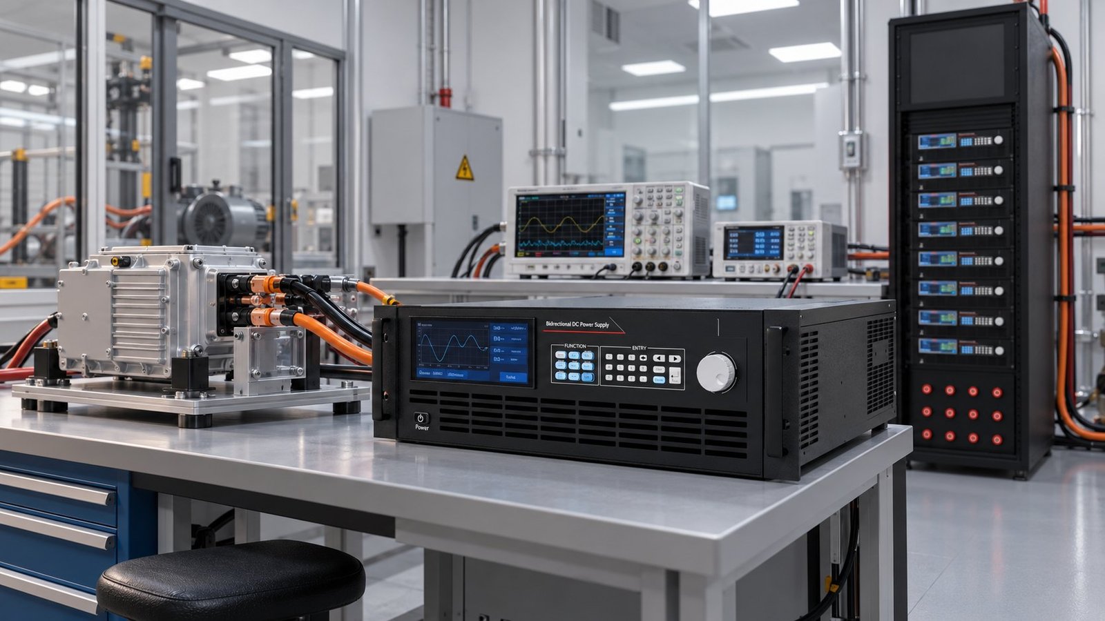
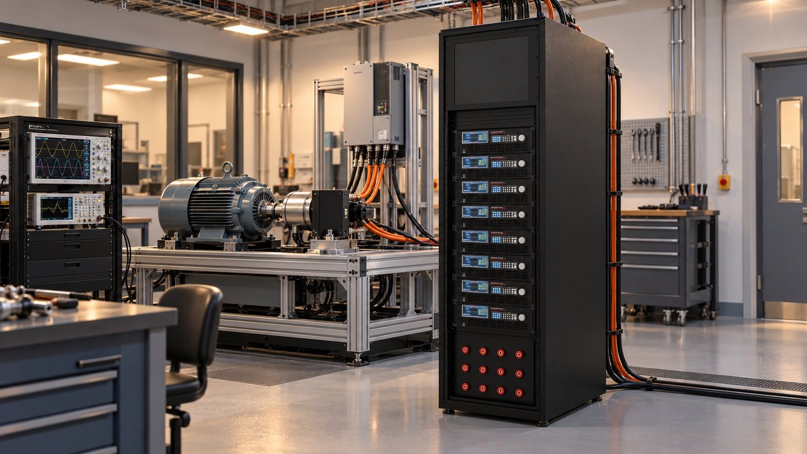
For a 1500 V DC inverter test, set the DC source at the declared operating point and measure voltage at the inverter terminals. Provide source headroom, a calibrated voltage channel, controlled load switching and a return path for energy released during the step.
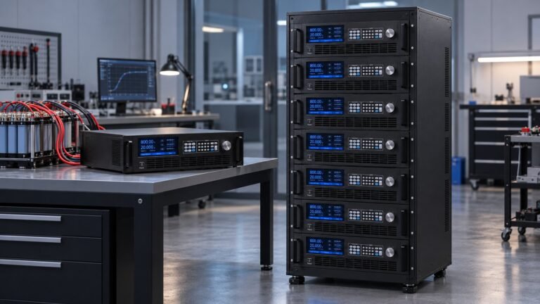
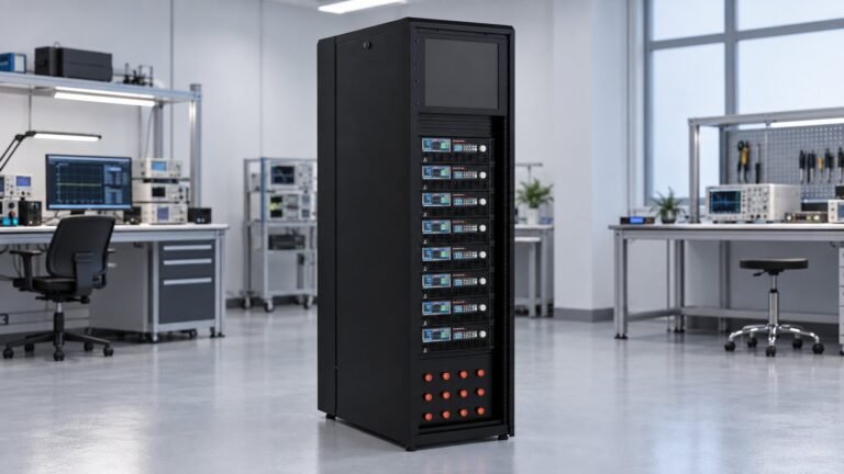
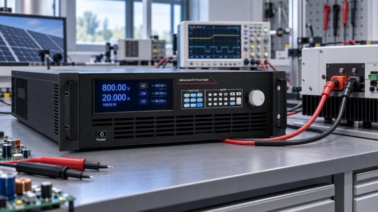
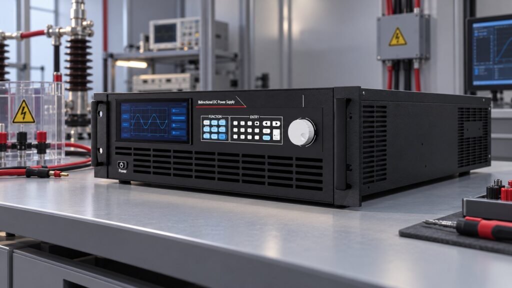
Ultra’s N35500 bidirectional and regenerative DC power supply classes cover 360 V, 500 V, 750 V, 1,000 V, 1,500 V and 2,250 V. Listed CV accuracy is ≤0.02% + 0.02% F.S. Use the High Voltage DC Power Supply Selection Guide to check voltage headroom before fixing the configuration.
| Bench item | Minimum definition | Use when |
|---|---|---|
| DC source | Declared bus voltage plus operating headroom | Testing the highest input condition |
| Voltage channel | Calibrated instantaneous measurement | Capturing transient peak and recovery |
| Sampling | No less than 10 kHz | Recording the full switching event |
| Load control | Full-load-to-zero and zero-to-full commands | Testing both transfer directions |
| Energy path | Bidirectional or regenerative handling | Returning energy during load release |
What is the repeatable load-transfer sequence?
Use separate full-load-to-zero and zero-to-full sequences, with three repetitions in each direction. FprEN IEC 62109-2:2026 identifies Clause 4.4.4.200 for stand-alone inverter load transfer and Clause 4.7.201.4 for transient output voltage.
- Stabilise the DC bus at the selected voltage and verify the measurement channel against its calibrated reference. Failure mode: source regulation drift makes the result non-repeatable.
- Apply the defined full load, then command full-load-to-zero. Failure mode: an out-of-phase transfer produces a transient that does not represent the intended switching event.
- Return to the defined operating state and repeat the same direction twice. Failure mode: cumulative overvoltage beyond the clause limit invalidates the sequence.
- Establish the stable zero-load condition, then command zero-load-to-full-load. Failure mode: delayed load application hides the inverter’s actual response.
- Repeat the reverse direction twice more while sampling instantaneous voltage at no less than 10 kHz. Failure mode: insufficient sampling misses peak overshoot or shortens the measured recovery interval.
- Save raw channels and one annotated 1,500 V waveform for each direction. Failure mode: missing trigger timing prevents an auditor from identifying the relevant load step.
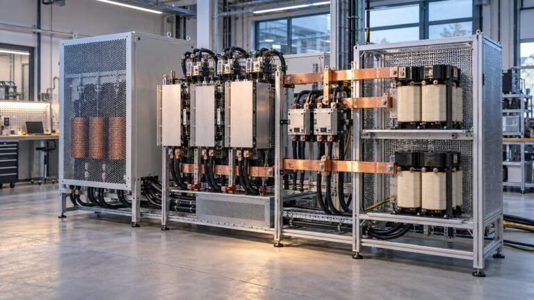
If the load release returns energy to the source, specify a regenerative dc converter path before running the sequence. Keep the source voltage, trigger settings and load command unchanged across all repetitions.
Which waveform evidence decides pass or fail?
Judge the trace against the time-window limits in Clause 4.7.201.4. Your annotated waveform should show the trigger, load transition, overshoot, recovery interval, applicable windows and final pass/fail result.
| Evidence | What you verify | Decision |
|---|---|---|
| Trigger marker | Exact instant of the load command | Reject ambiguous timing |
| Overshoot marker | Peak instantaneous voltage | Check against the applicable limit |
| Recovery marker | Return into the permitted window | Measure the clause time interval |
| 90–110% window | Primary specified transient band | Pass only when the time condition is met |
| 85–110% window | Secondary permitted band | Pass only when the time condition is met |
Ultra’s representative transient recovery is <4.5 ms for a 10–60% step. Treat that figure as source capability information, not as the inverter’s compliance result. The DUT waveform remains the evidence, and an out-of-phase transfer or cumulative overvoltage beyond the clause limit is a failure trigger.
FAQ: revised inverter safety testing
Does the second edition replace IEC 62109-2:2011?
Yes. The IEC 62109-2:2026 PRV | IEC page identifies the second edition as replacing the 2011 edition. Confirm the final published wording before issuing a compliance report.
How many load-transfer repetitions are required?
Repeat full-load-to-zero three times and zero-to-full three times. Keep source voltage, trigger timing and sampling settings unchanged.
What sampling rate should you use?
Sample instantaneous voltage at no less than 10 kHz. Use a higher rate when switching edges or instrument bandwidth could make the record insufficient.
How should you close the test plan?
Close the record with source setting, load-step direction, three-run results, sampling rate, annotated waveform and failure disposition. Keep the 2026 revision separate from MPPT testing, IEC 63409-3 and generic inverter-selection work.
For an ac to dc voltage converter supporting this bench, review UltraPower’s ac to dc voltage converter range →