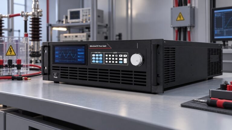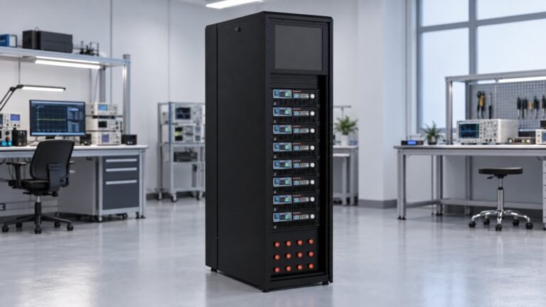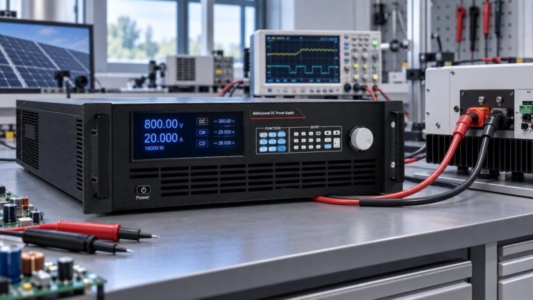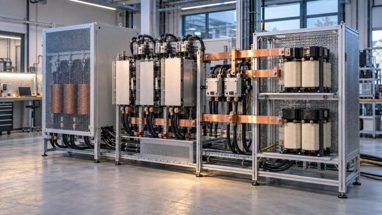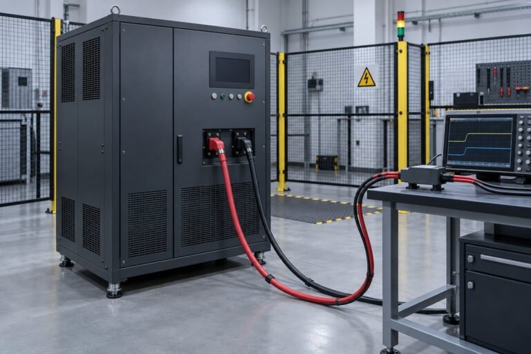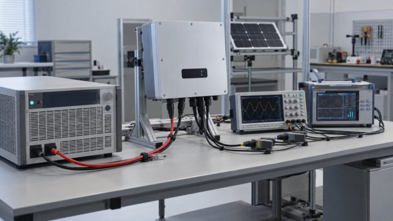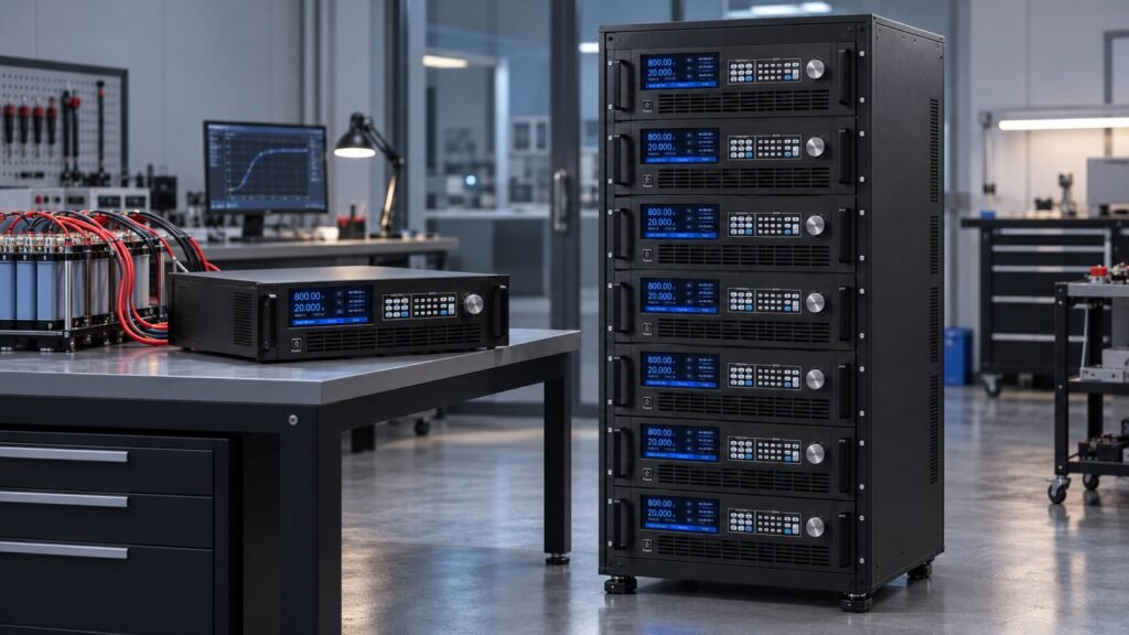
A regenerative dc converter replacement should be selected from measured source and sink limits, not the old unit’s nameplate alone. Record your DUT voltage window, positive and negative current, returned power, transient response, operating mode, parallel topology and control interface, then test the protection margin before approving the new platform.
Chroma says its NHR 9300 systems have been discontinued. Its 62000D replacement range covers 6–45 kW, up to 2,000 V and 540 A, with transient response below 1.5 ms and grid regeneration up to 93%. This worksheet applies that replacement logic to your test bench. Prepared by Ashkan, power supply engineer.
What must you measure before replacing a regenerative dc converter?
Replacement starts with a measured profile. A regenerative dc converter is suitable only if its voltage, bidirectional current, returned-power, crossover and protection limits cover your DUT at its worst transition.
Record the DUT terminals, not only the instrument display. Include cable drop, current peaks, pulse duration and the highest returned-energy event. If your voltage margin is still open, use the High Voltage DC Power Supply Selection Guide before choosing a voltage class.
Use this selection worksheet
Complete every row from measured waveforms or the DUT specification. A catalogue maximum is not a substitute for the operating point you must accept.
| Worksheet field | What to record | Decision or use when |
|---|---|---|
| DUT voltage range | Minimum, nominal and maximum DC bus voltage | Choose a rated class above the measured maximum, including your OVP margin. |
| Positive current | Source current, peak value and duration | Confirms the converter can deliver the charge or acceleration profile. |
| Negative current | Sink current, peak value and duration | Confirms reverse-current capability during discharge or regeneration. |
| Peak returned power | Highest V × |I| event and its duration | Sizes the sink stage and grid-regeneration path. |
| Response time | Command step, crossover time and recovery limit | Rejects a platform that misses the DUT transient window. |
| Operating mode | CC, CV, CP or CR, plus transition rules | Matches control behaviour to the converter, battery, inverter or motor drive. |
| Parallel topology | Single unit, master/slave or cabinet count | Defines how current, protection and control are shared. |
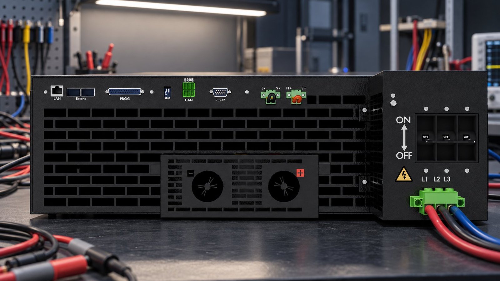
| Control interface | LAN, RS232, RS485, CAN and command protocol | Preserves your automation rack and test-sequence integration. |
How should you compare source-and-sink architectures?
Compare the energy path and the scaling method together. Matsusada’s PBR page shows one unit that can source and sink, while ten units scale to 150 kW. Chroma describes modular parallel operation for much larger systems. Regatron confirms that dynamic source/sink behaviour matters for inverter, charger and DC/DC validation.
For a bidirectional converter test supply, a single unit reduces coordination between separate source and load controls. A parallel cabinet becomes the better choice when your negative-current peak or returned-power duration exceeds one module’s limit.
| Architecture | Evidence to check | Use when |
|---|---|---|
| Single source-and-sink unit | One control loop handles positive and negative current | Your DUT stays within one unit’s voltage, current and power envelope. |
| Parallel modular platform | Master/slave or master/master coordination, shared protection and current balance | Your required source or sink power exceeds one unit, but the profile can be partitioned. |
| Legacy separate source and load | Independent setpoints, interlocks and energy path | You must retain existing hardware temporarily or the DUT requires different source and sink voltage ranges. |
What happens when returned power exceeds sink capability?
If returned energy exceeds sink capability, the DC bus rises until the overvoltage protection threshold trips. The test then aborts, or the DUT sees an unsafe transient before protection acts.
This failure often appears during source and sink testing because the average power looks acceptable while a short reverse-current pulse exceeds the sink stage. Check regenerative converter efficiency at the actual voltage and current point, not only the headline percentage.
- Measure reverse current at the DUT terminals during the fastest load release. Failure mode: a slow logger hides the peak and understates sink demand.
- Multiply the measured voltage and reverse current to obtain peak returned power. Failure mode: using average power misses a DC-bus overvoltage event.
- Compare the returned power and duration with the sink rating and regeneration path. Failure mode: treating a short overload rating as continuous capability causes repeated trips.
- Set OVP below the DUT’s absolute maximum while leaving normal transient headroom. Failure mode: an OVP threshold set too high protects the converter too late.
- Repeat the test at the highest bus voltage and worst regenerative profile. Failure mode: passing a steady-state test does not prove crossover protection.
When the reverse waveform is unclear, use the regenerative dc converter guide to separate DC-bus behaviour from AC-side regeneration losses.
See also: ac to dc voltage converter
What does a real N35500 replacement size look like?
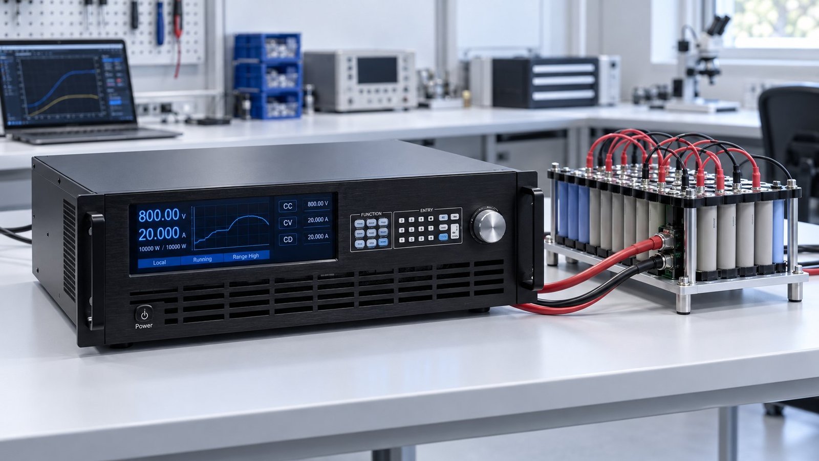
Our N35500-1000 sizing record covers an 800 V DUT bus at +50 A source and −50 A sink. That equals 40 kW in either direction, with 93% measured regenerative converter efficiency, a 4.5 ms measured source-to-sink crossover and an 880 V OVP threshold.
The 1,000 V class leaves 200 V above the operating point, while the 42 kW platform rating leaves 2 kW above the 40 kW test point. The record also includes the 0.02% F.S. voltage accuracy target and the complete waveform at the DUT terminals.
N35500 sizing record
| Measured item | Recorded value | Selection decision |
|---|---|---|
| DUT operating point | 800 V, +50 A / −50 A | Covers a 40 kW source and 40 kW sink profile. |
| Bidirectional power | 40 kW | Leaves 2 kW below the 42 kW platform rating. |
| Regenerative converter efficiency | 93% at the recorded return point | Use the measured value for returned-energy and cooling calculations. |
| Crossover time | 4.5 ms, measured from 10% to 60% current | Meets the ≤5 ms dynamic target for this configuration. |
| Protection threshold | 880 V OVP | Provides 80 V above the operating point while remaining below a 900 V DUT limit. |
Regenerative DC Converter Replacement FAQ
Does the voltage class decide the replacement?
No. The voltage class must cover the DUT range, but the negative-current peak, returned power, transient response and OVP setting decide whether the platform is safe for the profile.
How do you preserve automation during migration?
Map the legacy LAN, RS232, RS485 and CAN connections before removing the old unit. Confirm command behaviour, status polling, fault reporting and interlock timing with the new control interface.
Which standards belong in the acceptance record?
Name the standard that governs your DUT. PV inverter work may require EN 50530 profiles, EV work may require the applicable SAE or IEC document, and equipment safety evidence should identify IEC 61010-1.
Choose the replacement from measured evidence
A defensible replacement record contains the DUT voltage window, positive and negative current, returned-power peak, crossover result, operating mode, topology, interface and protection threshold. Use that worksheet to compare our ac to dc current converter systems and specify the platform that covers both quadrants →