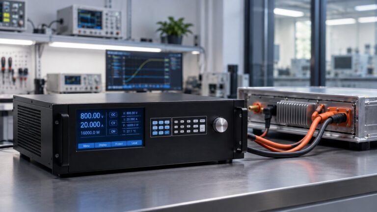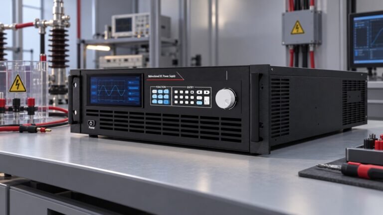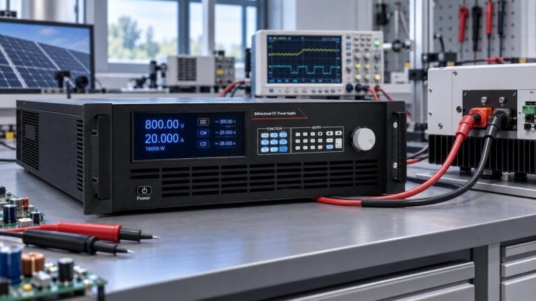
A high-capacity bidirectional DC power supply is a system-sizing decision, not simply a larger benchtop instrument. The German Search Console query “bidirektionale dc-stromversorgung mit hoher kapazität” translates to “high-capacity bidirectional DC power supply”. That English phrase is the target for this translated page.
You need to define voltage class, current, continuous and transient power, parallel topology, regenerative flow, cabinet service and fault containment before requesting a quotation. This guide keeps the focus on that architecture. It uses current figures from GW Instek, Chroma and Ultra Power Systems to show how a test bench grows into a controlled source-and-sink installation.
How to size a high-capacity bidirectional DC power supply
Begin with the device under test rather than the catalogue power rating. Record the minimum and maximum DC voltage, polarity, steady current, peak current and the duration of every excursion. A 1,000 V bus at 300 kW requires 300 A. The same power at 750 V requires 400 A. That difference changes the converter class, busbar size, protection settings and cabinet heat load.
Define the voltage envelope first
Choose a voltage class that leaves control headroom without forcing unnecessary insulation and clearance. Ultra Power Systems works across 360 V to 2250 V classes. Its 2250 V reference envelope covers 14–420 kW of bidirectional output and up to 2,400 A in a cabinet. Treat those figures as an architecture range, then confirm the exact operating window, ripple, response time and derating for your test profile.
Separate continuous power from transient power
A converter may need 180 kW continuously, 300 kW for 20 seconds and 420 kW during a fault or motor-braking event. Put each condition into the specification. State whether the peak is sourced, sunk or both. Also state the repetition rate. A ten-second pulse every five minutes creates a different thermal problem from a ten-second pulse every twenty seconds.
- Nominal, minimum and maximum voltage in volts, including overshoot limits.
- Continuous and transient current in amps, with duration and repetition rate.
- Source and sink power in kW, including the required regeneration efficiency percentage.
- DC ripple, control response time, isolation, precharge and emergency-stop behaviour.
- Required expansion point, such as 600 kW, 1 MW or a larger rack-level installation.
See also: IEC 61000-4-29 DC Power Supply: Test Bench Guide
Choose the source-and-sink topology
A regenerative DC source sink combines controlled sourcing with controlled absorption. That matters when your device returns energy during braking, discharge or conversion. It can reduce heat rejected into the room, but regeneration does not remove the need to size the AC interface, protection and cooling system for the highest returned power.
Use parallel capacity deliberately
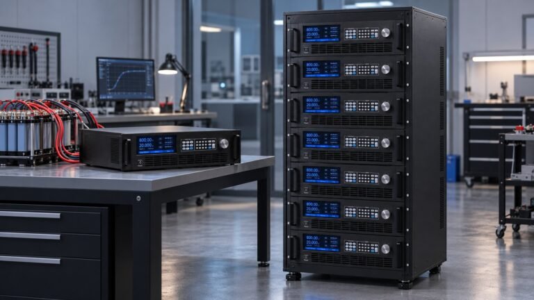
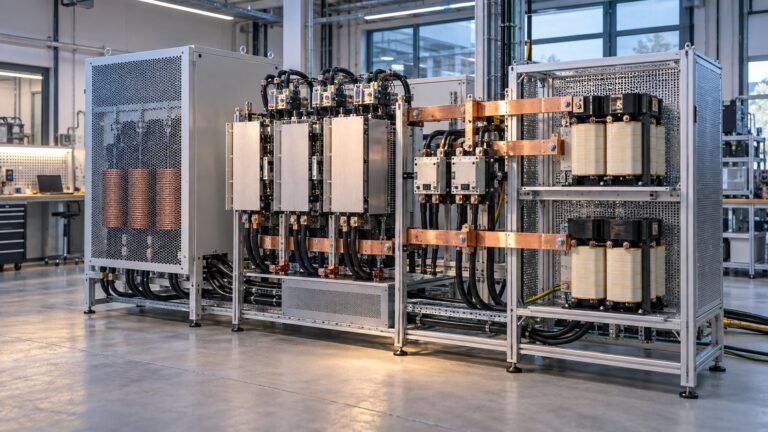
A parallel DC power supply gives you a path from a single test station to a multi-cabinet platform. The master-slave scheme, current sharing, start-up sequence and failure response must be specified. GW Instek’s August 2026 announcement reports 20 kW and 30 kW models in 500 V, 750 V, 1000 V, 1500 V and 2250 V classes. Up to ten units of the same model can operate in parallel for as much as 300 kW, with maximum output current reported at 510 A.
That approach suits a staged laboratory where the first installation is below 300 kW. It may not suit a high-voltage DC test system that needs rack-level redundancy, high pulse current or a defined maintenance bypass. In practice, you should compare the cost of additional modules with the cost of a common DC bus, switchgear, cooling and controls.
Check the regeneration path
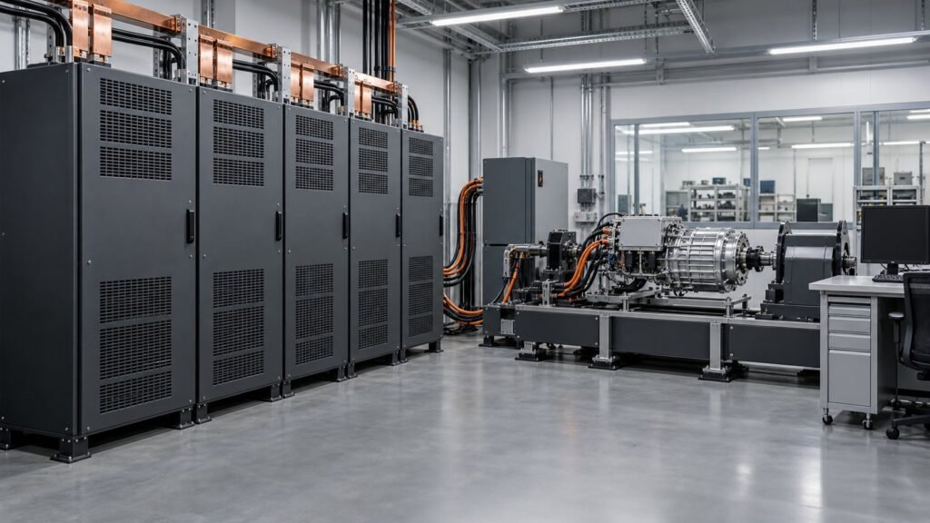
GW Instek reports up to 93% feedback efficiency for its RBS regenerative platform. The Chroma 62450D-2000HL listing reports a 2,000 V, ±60 A, ±45 kW high range, a 650 V, ±180 A, ±45 kW low range and regeneration up to 94%. It also lists 360 kW per rack and up to 1.8 MW across racks. These figures show why the source rating alone is not enough. Ask for the sink rating, regeneration limit, grid interface and thermal behaviour at your actual duty cycle.

Design the cabinet and protection layer
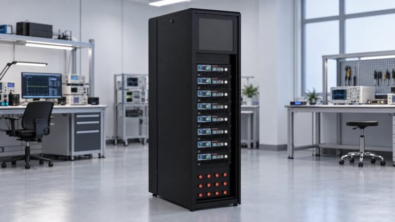
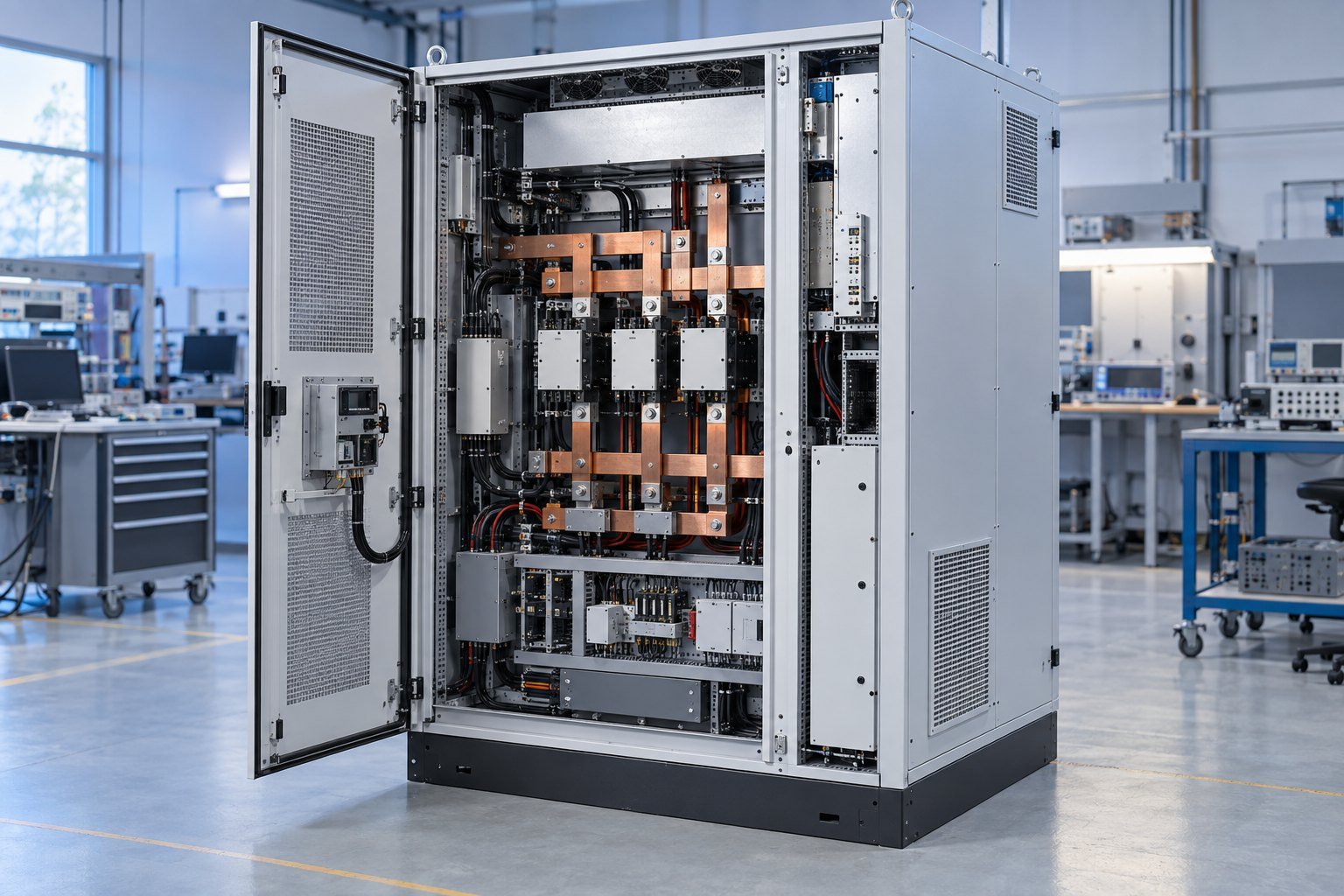
At cabinet scale, usable power depends on more than converter modules. Confirm incoming AC service, cable routes, airflow, ambient temperature, floor loading and access for replacement. A 420 kW cabinet at 1,000 V carries 420 A before margin. A 2,400 A cabinet rating can support a different voltage-power combination, but only if the bus, protection and thermal design match it.
Fault containment deserves its own design review. Specify DC fuses or breakers, precharge, contactor sequencing, insulation monitoring, discharge time and emergency isolation. Define what happens after an over-voltage, over-current or over-temperature trip. GW Instek lists OVP, OCP and OTP protection on the RBS platform, but your integrated installation still needs a coordinated protection study.
For photovoltaic work, identify whether EN 50530 dynamic MPPT testing applies. For vehicle and charger work, name the relevant SAE and IEC procedures in the test plan. Do not treat a voltage label as proof of compliance. Your quotation should state the interface, measurement method, ripple limit, response-time requirement and calibration responsibility.
- Map the DUT voltage and current envelope, including ten-second and one-minute events.
- Calculate source and sink power separately at the lowest operating voltage.
- Select a single cabinet or parallel topology with the next expansion stage documented.
- Review AC service, regeneration, protection, cooling and maintenance access together.
- Freeze the control, logging and compliance requirements before comparing prices.
See also: ac to dc converter regeneration commissioning guide
An anonymised sizing example for the quotation
Consider an anonymised battery-converter programme with an 800 V nominal bus, 900 V maximum test voltage, 300 kW continuous source power and a 450 kW source pulse lasting ten seconds. The continuous current is 375 A at 800 V. The pulse current is about 563 A. A 420 kW cabinet may cover the steady requirement but cannot be treated as the sole source for that pulse without confirming overload capability and derating.
The same line must absorb 220 kW for 30 seconds every two minutes. Its average sink power is 55 kW, but the DC and grid interfaces still need to handle the 220 kW event. If the system returns 85% of that absorbed energy, each event sends about 1.56 kWh back to the grid. The quote must therefore state peak sink power, regeneration limit and the permitted duty cycle.
Make expansion part of the first quote
The laboratory plans to reach 600 kW within eighteen months. We would ask for a 1000 V class architecture with a documented parallel path, spare cabinet positions, common controls and AC service reserved for the next stage. The first purchase may be smaller than the final system, but the bus, protection zones and cooling strategy should not force a redesign.
Include the calculation sheet with the request. Our DC power specification glossary helps align terms such as continuous power, peak power, ripple and regeneration before the engineering review. This prevents a 300 kW requirement from being quoted as a simple 300 kW nameplate.
FAQ: high-capacity bidirectional DC systems
When should you move beyond one benchtop unit?
Move when the test requires more than one voltage-current envelope, repeated regenerative events, cabinet service or future power above the single-unit rating. At that point, topology and protection affect the result as much as the converter.
Is higher regeneration efficiency always better?
Not by itself. Compare the stated efficiency with the returned-power limit, duty cycle, grid interface and cooling requirement. A 93% or 94% figure is useful only when it applies to your operating voltage and sink profile.
How much margin should the quotation include?
Specify margin from measured test data, not a generic percentage. Include voltage overshoot, current peaks, pulse duration, ambient temperature, expansion power and the effect of parallel-module failure.
Conclusion — Specify for expansion
A high-capacity bidirectional DC power supply should be quoted as a source-and-sink system with a defined voltage class, current envelope, duty cycle, regeneration path and fault strategy. GW Instek shows the value of 20 kW and 30 kW building blocks up to 300 kW. Chroma demonstrates rack scaling to 360 kW and 1.8 MW. Ultra Power Systems provides 360 V to 2250 V classes, 14–420 kW bidirectional output and up to 2,400 A in a cabinet. For a system matched to your present test and next expansion stage, submit the calculated envelope through our high-capacity bidirectional DC power supply quotation service →