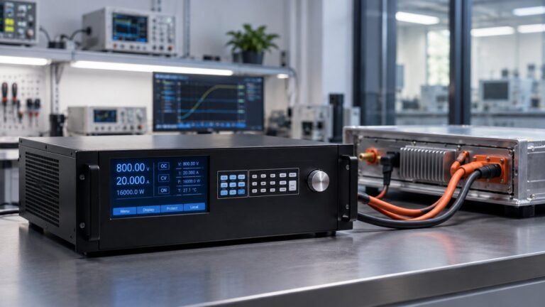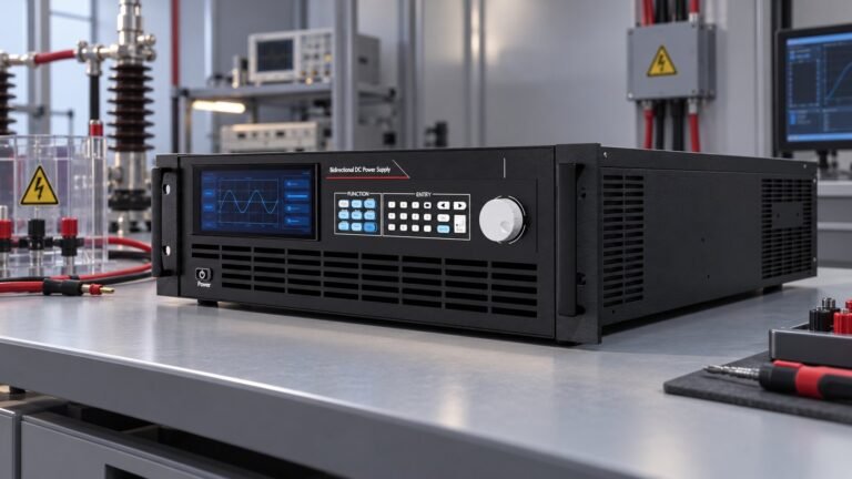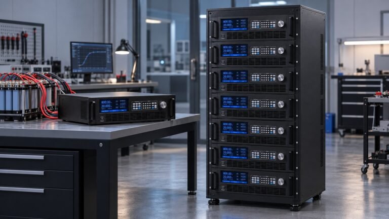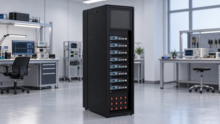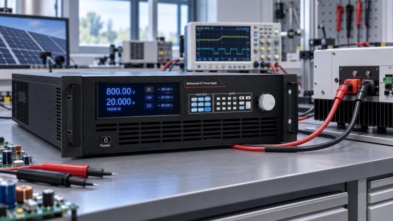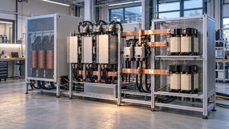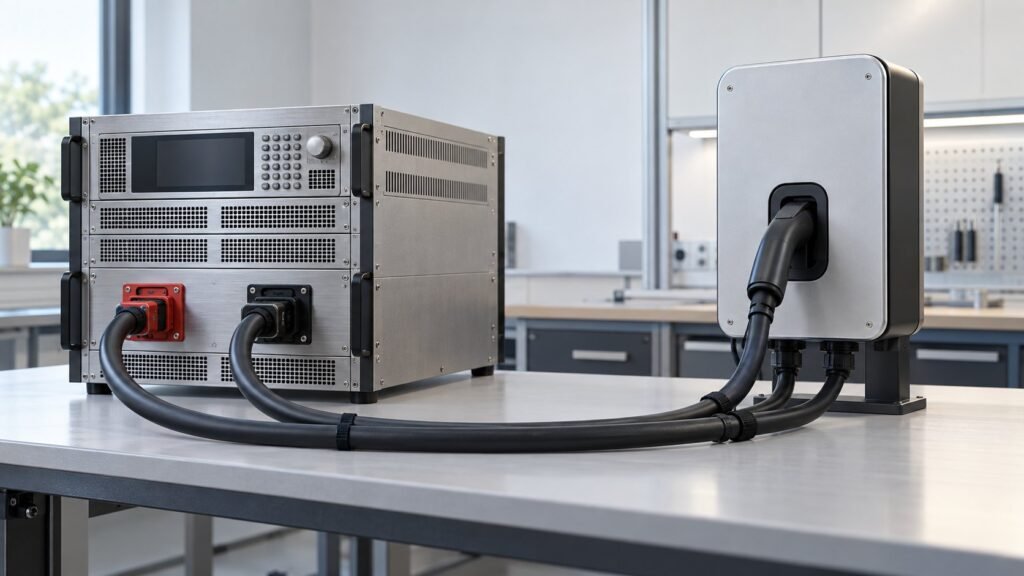
Ultra power solutions for EVSE testing combine a bidirectional DC source and sink with traceable measurements for IEC 61851-23:2023. Your bench should cover Clause 102 source-sink behaviour, 101.2 thermal management, Annex DD control, Annex EE artificial loads, and Annex HH touch-current evidence across the DUT’s voltage and current envelope.
Generic pages such as About – UPS Dealers, UPS Repair, UPS AMC and Ultra Power Solutions | Solar Panel Company in Pune address UPS or solar contexts. They do not map the EVSE-specific evidence missing from Clause 102, Annex EE, and Annex HH. This guide stays on equipment, thermal, artificial-load, and touch-current testing.
What does IEC 61851-23:2023 require from your bench?
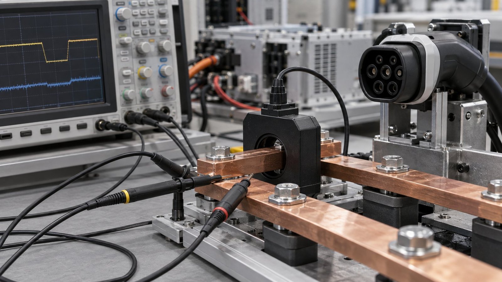
IEC 61851-23:2023 covers EVSE with side A up to 1,000 V AC or 1,500 V DC, and side B up to 1,500 V DC. The standard’s bidirectional power-transfer requirements apply to system A. Use the IEC publication as the governing source, then turn each applicable test into a measured source-sink record.
Your bench therefore needs controlled DC sourcing, controlled sinking, voltage and current capture, transient recording, thermal-state logging, and touch-current measurement. The objective is not a product demonstration. It is evidence that links the DUT condition, stimulus, response, and result.
See also: LV123 LV148 Test Power Supply Requirements
How should ultra power solutions implement Clause 102?
IEC 61851-23 Clause 102 compliance tests should run on an instrumented bidirectional bench with the DUT voltage, current, direction, waveform, and protection response recorded for every run. Specify the voltage class before you specify power.
| Voltage class | Use when |
|---|---|
| 360 V | Low-voltage, high-current pack and module testing. |
| 500 V | 400 V-architecture EV packs, DC-DC converters, and motor drives. |
| 750 V | 800 V EV architectures, chargers, and traction inverters. |
| 1,000 V | High-voltage EV packs, ESS strings, and DC fast-charging equipment. |
| 1,500 V | Utility PV strings, BESS, and grid-scale converters. |
| 2,250 V | Long PV strings and high-voltage power-electronics tests. |
- Set the source or sink to the DUT voltage and current operating point. Failure mode: an unsuitable voltage class or current range invalidates the test envelope.
- Apply the Clause 102 power profile and capture voltage and current at the DUT terminals. Failure mode: inadequate sampling hides a transient or understates the response time.
- Command source-to-sink and sink-to-source transitions. Failure mode: reversal overshoot can trigger OVP or OCP before the DUT reaches its intended state.
- Repeat the profile at defined thermal states and record the thermal condition beside each waveform. Failure mode: thermal drift can change current regulation or protection timing.
- Store the waveform, command file, instrument settings, touch-current result, and pass/fail decision together. Failure mode: an incomplete record cannot support a repeatable compliance review.
The EV Charger (BOBC) Test Power Supply lists 360 V, 500 V, 750 V, 1,000 V, 1,500 V, and 2,250 V classes. Its published figures include a dynamic response of ≤5 ms and accuracy of 0.02% F.S. Link the selected class and measured response to the DUT record.
See also: Battery Simulator for BMS Testing Under GB/T 47136
How do 101.2, Annex DD, Annex EE, and Annex HH change the test?
IEC 61851-23:2023 expands the bench beyond a voltage-and-current check. Section 101.2 adds thermal management evidence, Annex DD addresses bidirectional control, Annex EE introduces artificial test-load requirements, and Annex HH gives touch-current and touch-impulse-current guidance.
What should 101.2 thermal management evidence show?
Record the DUT operating point, ambient condition, thermal state, duration, and measured electrical response. Repeat the same electrical profile after thermal stabilisation so you can identify drift rather than treating temperature as a note outside the test record.
How should Annex DD bidirectional control be tested?
Exercise both power directions with commanded reversals and record the crossover waveform. Your evidence should show direction, reversal time, peak voltage, peak current, recovered energy, and any protection response.
What does Annex EE require from an artificial test load?
An EVSE artificial test load must reproduce the electrical transition required by the test, not just absorb steady power. Program the load step or ramp, record its timing, and compare the DUT response with the applicable pass criterion.
How should Annex HH measurements enter the record?
Place touch-current and touch-impulse-current measurements beside the corresponding DUT state and waveform. Do not leave them as a separate instrument printout with no link to the source-sink event.
Which traceability fields prove a bidirectional power transfer test?
A bidirectional power transfer test is defensible when every result connects the DUT condition to the commanded waveform and measured response. Use a traceability table like this for each voltage class and thermal state.
| DUT voltage and current | Source/sink direction | Waveform | Sampling bandwidth | Thermal state | Touch-current measurement | Pass/fail evidence | Decision/use when |
|---|---|---|---|---|---|---|---|
| Commanded and measured V and A at the DUT terminals | Source to DUT | Steady DC and programmed load step | Document the bandwidth used to resolve the ≤5 ms response | Initial, stabilised, and defined hot condition | Baseline touch current | Measured values, instrument settings, and criterion | Use for each Clause 102 operating point |
| Pre-transition and post-transition V and A | DUT to sink, then sink to DUT | Controlled ramp, step, or reversal | Capture crossover, overshoot, and recovery | Repeat after thermal stabilisation | Touch current and touch-impulse-current capture | Reversal time, peak overshoot in volts, and protection response | Use for the bidirectional power transfer test |
| Artificial-load command and DUT response | Sink transition or source transition | Annex EE load profile | Record the setting and trigger point | Record the state at transition | Measurement linked to the same timestamp | Pass/fail decision with waveform and event log | Use when an artificial test load changes state |
Failure box — artificial-load transitions can expose protection interactions. A rapid load change can create voltage overshoot or current demand beyond the programmed envelope. That event may trigger OVP, OCP, OPP, UVP, or UCP. Record whether the protection response is expected, premature, latched, or recoverable.
Ask Ultra Power Systems for a real N35500 trace showing the voltage class, reversal time, peak overshoot in volts, recovered energy in watt-hours, and protection response. A representative trace is more useful than a nominal specification when you are reviewing a failing transition →
What do engineers ask about ultra power solutions?
Which voltage class should you specify first?
Specify the highest DUT bus voltage first, then confirm current and power. The available classes are 360 V, 500 V, 750 V, 1,000 V, 1,500 V, and 2,250 V.
What response and accuracy figures should you check?
Check the measured dynamic response against the published ≤5 ms figure and check measurement accuracy against 0.02% F.S. Record the test bandwidth and trigger settings with both results.
Why use a bidirectional source and sink?
A bidirectional instrument can source and absorb power in the same test sequence. That lets you capture reversal behaviour and recovered energy without changing to a separate electronic load.
How should you specify ultra power solutions now?
Write the requirement as a measured bench specification: IEC 61851-23:2023 scope, Clause 102 profiles, 101.2 thermal states, Annex DD reversals, Annex EE artificial-load transitions, Annex HH touch-current evidence, and protection-event capture. Then match the voltage class and current range to the DUT. The EV Charger (BOBC) power supply for bidirectional EVSE testing provides the relevant source-sink platform. For a configured test bench, request a quote for your voltage, current, and evidence requirements →
— Ashkan, power supply engineer