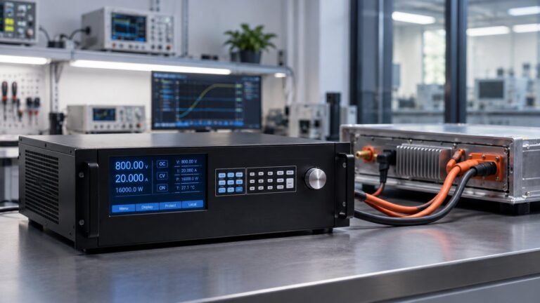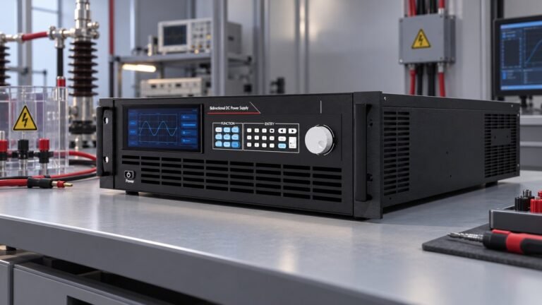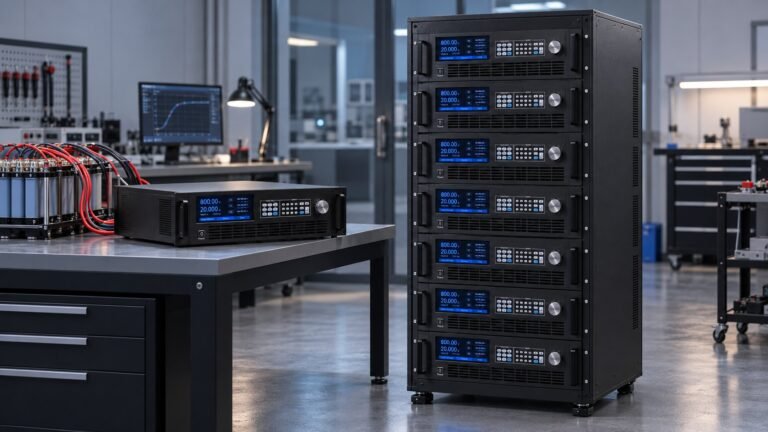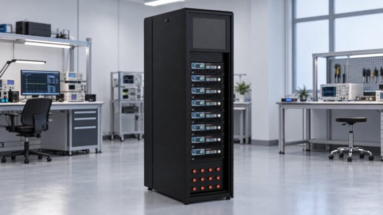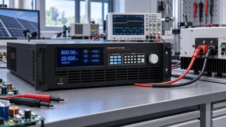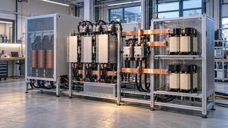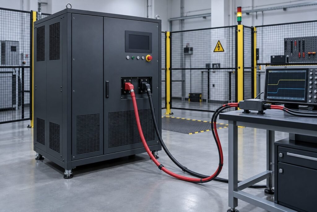
DC power supply ripple measurement on a 360–2250 V bidirectional output uses AC coupling, a defined 20 MHz bandwidth limit, a rated differential probe and a controlled load. Record mVp-p, mVrms, dominant FFT frequency, output voltage, current, temperature and cable length. Separate periodic PARD, broadband noise and load-reversal transients before you judge the result.
Generic bench guides rarely show a safe, repeatable method for high-voltage source-sink outputs. This procedure uses Ultra Power Systems equipment from 360 V to 2250 V, including the bidirectional and regenerative DC power supply range. It also applies the 2026 IEC boundary correctly. —Ashkan, power supply engineer
What should DC power supply ripple measurement separate?
A valid reading keeps periodic ripple, broadband noise and one-off load transients separate. OMCH’s Power Supply Ripple: What It Is, How to Measure It, and When It Matters provides the useful signal split; apply it here before calculating a pass or fail value.
| Signal | Typical signature | Report separately | Use when |
|---|---|---|---|
| Periodic ripple or PARD | Repeating waveform near the converter switching frequency | mVp-p, mVrms and dominant FFT frequency | Comparing steady-state output quality |
| Broadband noise | Non-periodic high-frequency content inside the selected bandwidth | Bandwidth, probe method and noise floor | Checking measurement repeatability or EMI-sensitive loads |
| Load transient | Single event during current reversal or a source-sink command | Peak excursion, duration and trigger condition | Assessing dynamic response rather than steady ripple |
For a PARD measurement, capture only a settled source or sink interval. A current reversal on a regenerative output can create a large but short event. Including that event in the same Vp-p reading makes a dynamic transient look like continuous ripple.
Which IEC standard applies to high-voltage ripple testing?
IEC 61000-4-17:1999+A2:2008 is the ripple reference: clauses 5, 7 and 8 define test levels, setup and procedure for low-voltage DC input ports. IEC 61000-4-29:2026 Clause 1 explicitly excludes ripple and points to IEC 61000-4-17.
The boundary matters for your report. Use IEC 61000-4-17 for the ripple method, then state that your 360–2250 V source-sink test is a product characterisation unless a named compliance plan says otherwise. Do not reuse an IEC 61000-4-29 bench guide as the ripple procedure.
See also: IEC 61000-4-29 DC Power Supply: Test Bench Guide
How should you configure a 360–2250 V test bench?
Configure the bench before energising: AC-couple the channel, enable the 20 MHz bandwidth limit, set probe attenuation to 1000:1, hold the load at 10 A, and record 23 ±2 °C ambient temperature with 2 m output cables.
| Output setpoint | Load condition | Capture setup | Use when |
|---|---|---|---|
| 360 V | +10 A source, then −10 A sink | AC coupling, 20 MHz, 1000:1 differential probe | Lowest-voltage system check |
| 1000 V | +10 A source, then −10 A sink | AC coupling, 20 MHz, 1000:1 differential probe | Mid-range comparison |
| 1500 V | +10 A source, then −10 A sink | AC coupling, 20 MHz, 1000:1 differential probe | High-voltage operating check |
| 2250 V | +10 A source, then −10 A sink | AC coupling, 20 MHz, 1000:1 differential probe rated above the test voltage | Maximum-voltage verification |
What probe connection is safe?
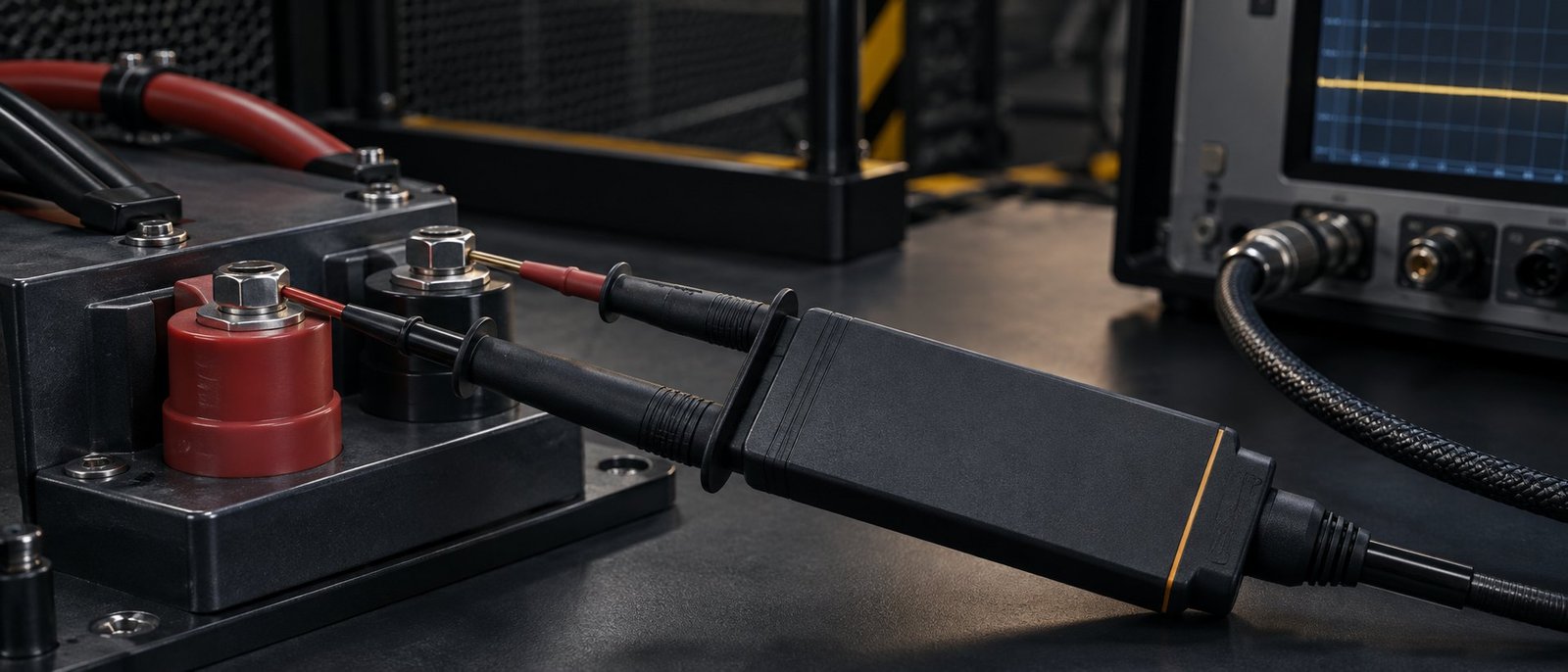
A grounded oscilloscope has earth-referenced BNC shells. Do not attach a standard probe ground clip to a 2250 V output. Check the differential probe high voltage rating, common-mode range, attenuation and transient category before energising. An incorrectly rated differential probe can invalidate the result or fail under overshoot.
SPR’s How to measure switching power supply ripple accurately explains why a long probe ground lead acts as an antenna. At high voltage, the failure is more severe: a false spike is triggered by probing a high-dv/dt source-sink output without a short ground connection or rated differential probe.
What repeatable procedure should you run?
Run the same sequence at 360 V, 1000 V, 1500 V and 2250 V. Repeat it in source and sink operation, but analyse each settled interval separately.
- 1. Confirm the circuit. Identify polarity, source direction, sink direction, output terminals and the 2 m cable length. Failure mode: an earth reference or polarity error changes the circuit before the scope is connected.
- 2. Set the operating point. Use the N35584-2250-130 and apply 10 A source current, then 10 A sink current after the output settles. At 2250 V, 10 A represents 22.5 kW; confirm the load and cables are rated for it. Failure mode: measuring a ramp or current reversal instead of steady ripple.
- 3. Configure the scope. Select AC coupling, the 20 MHz bandwidth limit, 1000:1 probe attenuation and a vertical scale that resolves millivolts. Failure mode: DC offset, excessive bandwidth or poor scale hides the comparison.
- 4. Connect with power removed. Place the rated differential inputs directly across the output terminals. Keep the connection short and do not use an earth-referenced clip. Failure mode: the grounded oscilloscope shorts the output or the probe exceeds its common-mode rating.
- 5. Check the noise floor. With the output disabled, capture the probe baseline at the same physical location. Failure mode: ambient pickup is reported as supply noise.
- 6. Capture a settled window. Record several switching cycles without a source-sink command, then calculate mVp-p, mVrms and the dominant FFT frequency. Failure mode: one narrow spike inflates the ripple result.
- 7. Repeat and document. Repeat both directions at all four voltages and log voltage, current, bandwidth, attenuation, temperature and cable length. Failure mode: two results appear comparable even though their test conditions differ.
How should you report a PARD measurement result?
Report the result with its complete test condition, not as a bare ripple number. Include the model, voltage, current direction, load current, coupling, bandwidth, attenuation, temperature, cable length, mVp-p, mVrms and FFT peak.
One recorded lab result for the 2250 V bidirectional DC power supply, model N35584-2250-130, was 82 mVp-p and 18 mVrms at 2250 V and +10 A source current. The capture used AC coupling, a 20 MHz bandwidth limit, a 1000:1 differential probe, 23 °C ambient temperature and 2 m output cables. The dominant FFT frequency was 100 kHz.
When is a spike not ripple?
A spike is a load transient when it appears only during current reversal or a source-sink command and disappears after the output settles. Report its peak and duration separately. If the spike remains periodic under a steady 10 A load, include it in the PARD result and investigate its FFT frequency.
After the measurement is stable, use the high-voltage DC power supply selection guide if you need to match voltage class, regenerative operation and load requirements to a wider test system.
See also: regenerative dc bidirectional source and sink
FAQ: DC power supply ripple measurement
Is the 20 MHz bandwidth limit always required?
Use the 20 MHz bandwidth limit when comparing a vendor ripple specification or repeating a production check. Open bandwidth only for a separate diagnostic capture, and label that result clearly.
Can you use a grounded probe at 2250 V?
No. Use a differential probe with a voltage and common-mode rating above the test voltage and expected overshoot. A grounded probe can create an earth fault through the oscilloscope.
Should regenerative load transients count as ripple?
No. A one-off event during source-sink reversal is a transient. Report it with its trigger, peak and duration, then report steady-state PARD separately.
What should your final report contain?
A defensible report identifies the N35584-2250-130, all four voltage setpoints, source and sink current, probe attenuation, AC coupling, 20 MHz bandwidth, temperature, cable length, mVp-p, mVrms, FFT frequency and any excluded load transient. Use the Ultra Power Systems DC power supply specification glossary to standardise terms across your report and procurement review →