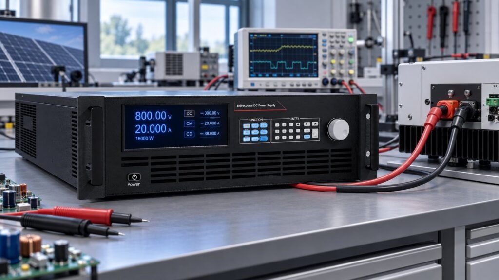
An IEC 63409-3 DC test setup is an auditable PV PCE bench that records the circuit and sensor positions, identifies the DC source or simulator, holds each active-power point for at least 60 seconds, and proves that source stability and cable drop do not alter the DUT result.
EVS-EN IEC 63409-3:2026 is valid from 16 February 2026 and covers steady-state and transient characteristics. Written from Ashkan’s power supply engineering perspective at Ultra Power Systems, this guide converts Clause 4.2, Table 1, Clause 5.1.2.4 and Clause 5.1.3 into procurement fields and acceptance evidence.
What must your IEC 63409-3 DC test setup record?
Your record must identify the test circuit, every sensor location, the source or simulator type, and the values required by Table 1. Clause 4.2 also requires the DC source not to influence the test result.
Turn Clause 4.2 into a procurement checklist
IEC 63409-3:2025 requires a reproducible measurement path. Draw the circuit before commissioning. Mark voltage and current sensors at the source, cable ends and PCE terminals. State whether you use a DC supply, battery simulator or another source. These are the IEC 63409-3 test requirements your acceptance file must preserve.
| Table 1 field | Record on the bench | Acceptance use |
|---|---|---|
| Udc_min | Lowest declared DC voltage | Checks the lower operating boundary |
| Udc_nom | Nominal DC voltage | Defines the reference operating point |
| Udc_max | Highest declared DC voltage | Checks the upper operating boundary |
| Smax | Maximum apparent power for the PCE test | Confirms source and wiring capacity |
| Pnom | Nominal active power | Sets the 100% power reference |
- Record the selected voltage class and the exact Udc operating point.
- Record the DC source or simulator type, control mode and operating range.
- Record voltage and current sensor locations, calibration identifiers and sampling settings.
- Record cable length, conductor size, connector type and measured voltage drop.
- Attach source-side and DUT-terminal waveforms to the final report.
See also: ev battery simulator
How do you run the Clause 5.1.2.4 power sequence?
Clause 5.1.2.4 requires active-power testing from 100% down to 10% in 10% steps. Hold every point for at least 60 seconds, and retain the measured operating values and failure status.
Use the sequence below for PV inverter PCE testing. The failure note beside each step gives your operator an auditable stop condition.
- Set 100% of Pnom and hold for at least 60 seconds. Failure mode — actual active power does not remain at the declared point or the waveform is still settling.
- Set 90% of Pnom and hold for at least 60 seconds. Failure mode — the source or DUT-terminal voltage moves enough to change the PCE result.
- Set 80% of Pnom and hold for at least 60 seconds. Failure mode — the current limit engages or clips the commanded operating point.
- Set 70% of Pnom and hold for at least 60 seconds. Failure mode — cable drop creates a different voltage at the PCE terminals than the reported source voltage.
- Set 60% of Pnom and hold for at least 60 seconds. Failure mode — the source control loop oscillates during the hold.
- Set 50% of Pnom and hold for at least 60 seconds. Failure mode — measured active power leaves the acceptance band or the PCE changes state unexpectedly.
- Set 40% of Pnom and hold for at least 60 seconds. Failure mode — the source cannot maintain the commanded voltage under the reduced power condition.
- Set 30% of Pnom and hold for at least 60 seconds. Failure mode — noise, ripple or measurement resolution prevents a stable result.
- Set 20% of Pnom and hold for at least 60 seconds. Failure mode — the PCE response changes when sensing moves from the source terminals to the DUT terminals.
- Set 10% of Pnom and hold for at least 60 seconds. Failure mode — the PCE cannot sustain the operating point or the final result is not reproducible.
How do you verify voltage-range operation under Clause 5.1.3?
Clause 5.1.3 requires you to test the declared voltage range at Udc_min, Udc_nom and Udc_max. Verify operation at the PCE terminals, not only at the DC source output.
| Voltage point | Test action | Pass or fail record |
|---|---|---|
| Udc_min | Apply the lower declared voltage and repeat the required operating point. | Pass only if the PCE operates correctly and the terminal voltage matches the recorded setup. |
| Udc_nom | Apply nominal voltage and repeat the reference power sequence. | Pass only if source and DUT-terminal measurements support the same result. |
| Udc_max | Apply the upper declared voltage within the selected class. | Pass only if the PCE remains controlled and no cable drop or source limit changes the result. |
Select the voltage class before you purchase the source. For a wider high-voltage decision, use the High Voltage DC Power Supply Selection Guide. Do not treat a catalogue maximum as proof that the PCE test range has been verified.
What evidence should an N35500 setup produce?
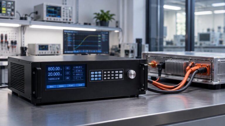
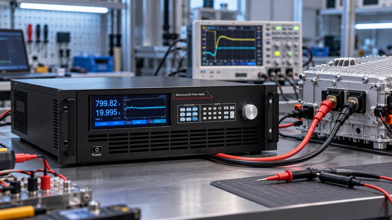
Our N35500 setup record uses an 800.00 V operating point within a selected 1000 V class and pairs the commanded value with measured source stability, settling behaviour and DUT-terminal voltage. The record must show the waveform, not just a setpoint screenshot.
| Evidence item | N35500 setup record | Decision rule |
|---|---|---|
| Selected voltage class | 1000 V class; 800.00 V operating point recorded | The class must cover Udc_min, Udc_nom and Udc_max. |
| Measured source stability | Peak-to-peak source-voltage variation over each 60-second hold | Reject the point if variation changes the measured PCE result. |
| Settling waveform | Step-response trace with the settling time marked | Do not start the 60-second hold until the waveform is settled. |
| Voltage at source terminals | Direct measurement at the N35500 output terminals | Use it to confirm the programmed source condition. |
| Voltage at DUT terminals | Direct measurement at the PCE DC input terminals | Use it to identify cable drop and terminal mismatch. |
| Exact failure trigger | Source instability or cable drop changes the PCE result after terminal-level measurement | Fail the point, correct the setup and repeat the complete measurement. |
Ultra Power Systems lists a representative response of ≤5 ms and voltage accuracy of ≤0.02% + 0.02% F.S. The platform context is 0–2250 V, across bidirectional and regenerative DC power supplies. These figures support source selection, but catalogue specifications alone do not establish IEC 63409-3 conformity.
When does source instability become a failed test?
The exact trigger is a changed PCE result caused by source variation or cable drop. If the result changes when you compare the source-terminal voltage with the DUT-terminal voltage, fail that point. Do not mask the difference with a software correction. Repair the measurement path and repeat the hold.
How should the source and return path be documented?
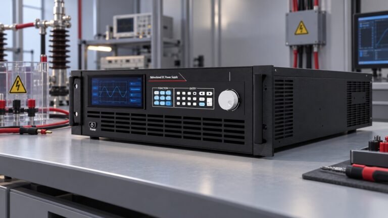
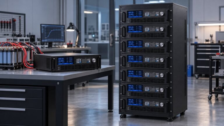
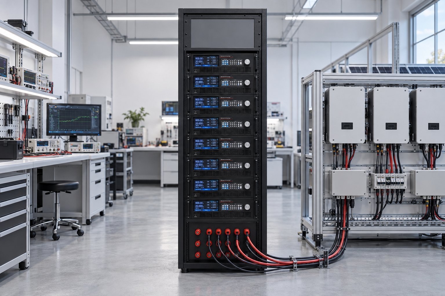
Document the complete DC energy path, including source, cables, PCE, returned energy and protection. A bidirectional source may need to absorb regenerated power, so specify the return path before the first test. The Regenerative DC Electronic Load for High-Power Testing is relevant when your bench must manage returned energy.
Record upstream conversion and regeneration separately from PCE performance. The ac to dc converter regeneration commissioning guide helps when the source is connected to a regenerative AC-to-DC system.
- Identify the source operating mode: source, sink or bidirectional.
- Record the maximum DC voltage, current and apparent power used in the test.
- Measure voltage at the source and DUT terminals under load.
- Store the settling waveform and the full 60-second hold trace.
- State whether regenerated energy returns to the grid, a load or an internal energy path.
See also: ac to dc current converter
IEC 63409-3 DC test setup FAQ
Does catalogue accuracy prove IEC 63409-3 compliance?
No. Accuracy and response specifications help you select equipment. Your report still needs measured source stability, terminal voltages, settling traces and repeatable PCE results.
How long should each active-power point be held?
Hold each point for at least 60 seconds under Clause 5.1.2.4, after the source and PCE have settled.
What should you do if source and DUT voltages differ?
Measure the cable drop, determine whether it changes the PCE result and fail the point if it does. Correct the wiring or sensing arrangement, then repeat the test.
Conclusion — approve the evidence, not the catalogue
A defensible IEC 63409-3 DC test setup links Clause 4.2 records to Table 1 values, the 100% to 10% sequence, Clause 5.1.3 voltage checks and N35500 waveform evidence. If you need a bidirectional or regenerative dc power source for this bench, specify the voltage class, measured terminal conditions and acceptance record before commissioning →