The August 2025 publication of T/CPSS 1014—2025 sets the cell-level reference for EV battery simulator accuracy: a simulator for nominal cell voltages up to 6 V and balancing currents up to ±5 A should deliver better than ±1 mV voltage accuracy, microsecond response capability, low ripple, low adjustment rate, low temperature coefficient, and verified EMC and safety.
The practical gap is between a millivolt-sensitive cell channel and a high-voltage pack simulator. Your acceptance test must keep those limits separate. A pack supply can meet its own tolerance while remaining unsuitable for a balancing-threshold test.
What does T/CPSS 1014—2025 require for cell simulation?
T/CPSS 1014—2025 applies to bidirectional cell simulators rated for nominal cell voltage no higher than 6 V and balancing current no greater than ±5 A. Its scope clause defines the covered equipment. Its technical-requirements clause sets better-than-±1 mV voltage accuracy, microsecond response capability, low ripple, low adjustment rate, low temperature coefficient, EMC performance and electrical safety. Its test-method clause provides the route for verifying those requirements.
The issuing body reports that products offering only 1–3 mV accuracy can distort BMS validation data. That makes T/CPSS 1014-2025 a useful specification reference whenever you assess cell emulator voltage precision, especially near a balancing boundary.
| Standard element | Practical limit | Acceptance question | Use when |
|---|---|---|---|
| Scope | Nominal cell voltage ≤6 V; balancing current ≤±5 A | Does the channel fall inside the standard’s application range? | Selecting cell-simulation hardware |
| Technical requirements | Voltage accuracy better than ±1 mV, microsecond response, low ripple, low adjustment rate and low temperature coefficient | Are the limits stated as measured results rather than display resolution? | Validating cell channels |
| Test methods | Defined verification of the technical requirements | Are voltage, current, temperature and load recorded with the trace? | Signing off a test bench |
| EMC and safety | Electrical safety and stable operation in electromagnetic environments | Are safety and EMC checks included in the acceptance record? | Commissioning laboratory equipment |
See also: lv123 automotive standard
How does EV battery simulator accuracy change from cell to pack?
EV battery emulator accuracy is a two-level claim. Cell simulation is judged in millivolts around BMS thresholds. Pack simulation is judged across hundreds or thousands of volts, dynamic recovery and a modelled voltage curve. The Medium article EV Battery Simulator: Scaling the Simulation from Cell-Level to Full Pack describes this scaling problem; your specification should preserve both measurement layers.
| Test layer | Platform or range | Accuracy and dynamic reference | Use when |
|---|---|---|---|
| Cell channel | Nominal cell ≤6 V; balancing ≤±5 A | Better than ±1 mV, microsecond response capability, low ripple and low temperature coefficient | Testing balancing logic and cell limits |
| Pack-level source | Ultra N35500 classes: 360, 500, 750, 1000, 1500 and 2250 V | ≤0.02% + 0.02% F.S. voltage accuracy; transient recovery <4.5 ms | Testing pack voltage control and dynamic events |
| Pack model | NS81000 battery simulation software | Custom measured curves for the pack profile | Running measured SoC, OCV or drive-cycle behaviour |
Ultra Power Systems lists the N35500 as a pack-level platform with six voltage classes from 360 V to 2250 V. Its specification is not a replacement for the cell-channel limit. Use the N35500 accuracy figure for pack acceptance, then verify each cell emulator against the tighter millivolt requirement.
If your pack voltage class is not yet fixed, use the High Voltage DC Power Supply Selection Guide to define the required range before writing the acceptance limits.
For the separate system-level test method, use Battery Simulator for BMS Testing Under GB/T 47136 after the cell-versus-pack accuracy split is defined.
What should a measured accuracy trace include?
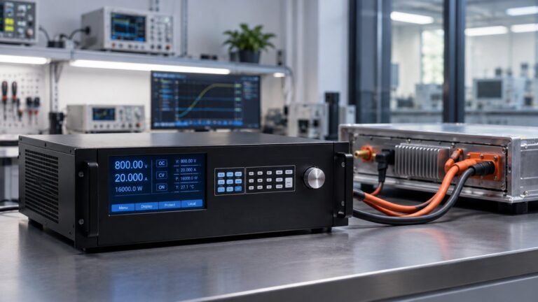
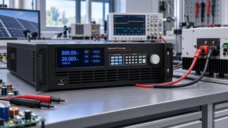
A measured accuracy trace must state the command, measured voltage, current, temperature, load and time base. For a 360 V-class pack test, specify 300.000 V, 20.000 A, 25 °C and a 15 Ω load, then plot measured voltage minus command in volts or millivolts. Report peak error, minimum error and recovery time.
| Trace field | Example record | Why it matters |
|---|---|---|
| Voltage command | 300.000 V | Defines the test point |
| Current | 20.000 A | Shows operating load |
| Temperature | 25 °C | Controls temperature-coefficient effects |
| Load | 15 Ω electronic load | Makes the operating condition repeatable |
| Measured output | Vmeas − Vset over time | Exposes static error and drift |
| Dynamic result | Peak error and recovery time | Checks the pack-level transient requirement |
- Stabilise the source at 300.000 V, 20.000 A, 25 °C and 15 Ω. Failure mode: an unrecorded temperature or load change can appear as voltage inaccuracy.
- Log the calibrated measurement and the front-panel reading together. Failure mode: relying on display digits can hide a measurement-chain offset.
- Run a controlled voltage step and capture the response trace. Failure mode: a slow response can miss the timing of a BMS hardware-in-the-loop event.
- Compare the measured extrema with the N35500 limit of ≤0.02% + 0.02% F.S. and the recovery target below 4.5 ms. Failure mode: mixing cell and pack limits can produce a false pass.
- Store the trace with instrument identity, date and conditions. Failure mode: an unrepeatable record cannot support a later BMS validation decision.
See also: dc power source
Which failure mode makes a millivolt error expensive?
An inaccurate cell setpoint can falsely trigger or miss a balancing threshold. If the BMS threshold is 3.650 V, a simulator output of 3.652 V may trigger balancing early, while 3.648 V may leave balancing inactive. The error is only 2 mV, but it changes the validation result.
This is why cell accuracy must be assessed at the threshold, under the intended balancing current and temperature. A pack-level result at 300 V cannot prove that a 3.650 V cell channel is within ±1 mV.
EV battery simulator accuracy FAQ
What cell voltage does T/CPSS 1014—2025 cover?
The scope covers nominal cell-simulation voltage up to 6 V and balancing current up to ±5 A.
Does N35500 pack accuracy prove cell accuracy?
No. N35500 pack accuracy applies to its pack-level operating range. Cell channels still require their own millivolt acceptance test.
When should you use NS81000 custom measured curves?
Use NS81000 when your pack test needs a measured voltage curve rather than a fixed DC setpoint, including custom OCV or SoC behaviour.
How should you specify the acceptance test?
Specify two linked records: a cell-channel trace against the better-than-±1 mV requirement, and a pack trace against the N35500 class, ≤0.02% + 0.02% F.S. accuracy and <4.5 ms recovery. Ashkan, power supply engineer, recommends attaching both traces to the test-bench approval record. For the complete platform, see the battery simulator DC power supply range →