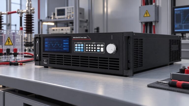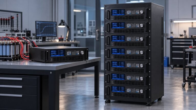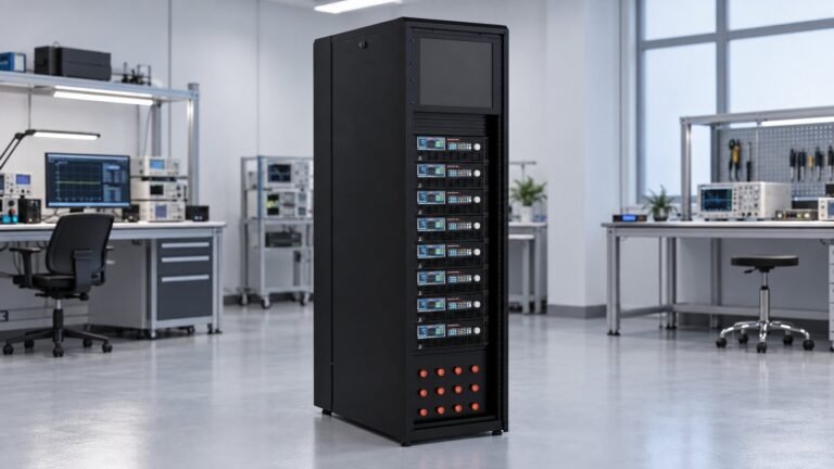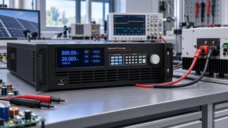
Bidirectional battery simulator transient response is the measured time and voltage error when your DUT reverses current from source to sink and back. Test it with a defined DC voltage, ±current step, calibrated cables, remote sense, oscilloscope trigger and protection state. Accept the trace by transition time, overshoot, undershoot and settling—not by a brochure label alone.
This guide turns published millisecond specifications into a repeatable acceptance test. It compares ActionPower NEXUS and TITAN data, then defines a named N35500 result at 500 V and ±35 A. The failure under examination is DC-link overshoot or control-loop oscillation when the DUT reverses faster than the simulator responds.
How do you measure bidirectional battery simulator transient response?
Bidirectional battery simulator transient response is the interval from a commanded current reversal to a stable voltage and current condition at the DUT terminals. Ashkan, power supply engineer at Ultra Power Systems, treats the source-to-sink and sink-to-source traces as separate acceptance events because cable inductance and control-loop behaviour can differ by direction.
For a battery emulator current reversal, record the current zero crossing, the first voltage peak, the final value and the time the waveform remains inside the agreed band. A fast command update does not prove a stable power stage. The DC link must remain controlled while the DUT changes from consuming to returning energy.
Which battery simulator response time should you compare?
Battery simulator response time must be compared with identical voltage, current, step amplitude and measurement bandwidth. The published figures below are useful references, but they are not interchangeable pass criteria.
| System or record | Published or measured figure | Use when |
|---|---|---|
| ActionPower NEXUS | Less than 2 ms from −90% to +90% full scale, less than 1 ms rise time, less than 1.5 ms recovery after a 50%-to-100% load step, ±5% full-scale dynamic overshoot and a 200 µs command-update rate. | Use as a high-dynamics reference. |
| ActionPower TITAN | 4.8 ms current switching, 24 V overshoot at 500 V applied and 22 V undershoot after sudden load removal. | Use as a voltage-error stress benchmark. |
| Ultra Power N35500 | At 500 V and +35 A ↔ −35 A, measured transition 4.8 ms and recovery 4.1 ms. Publish peak overshoot and protection state beside the trace. | Use as the named N35500 acceptance record. |
Ultra Power Systems publishes bidirectional and regenerative DC power supplies in 360 V, 500 V, 750 V, 1000 V, 1500 V and 2250 V classes. Each unit supports up to ±240 A, with a published transition of ≤5 ms, recovery below 4.5 ms, and OVP, OCP, OPP, UVP and UCP protection. Select the relevant class before scaling the test current.
How do you run a controlled source-to-sink switching test?
The source-sink switching time is only meaningful when the electrical path and trigger are documented. Use the following test definition for a repeatable N35500 result.
For higher-voltage platforms, confirm probe rating, creepage and the intended operating class using the High Voltage DC Power Supply Selection Guide before energising the bench. For automotive validation, record the applicable lv123 standard requirement in the same test header.
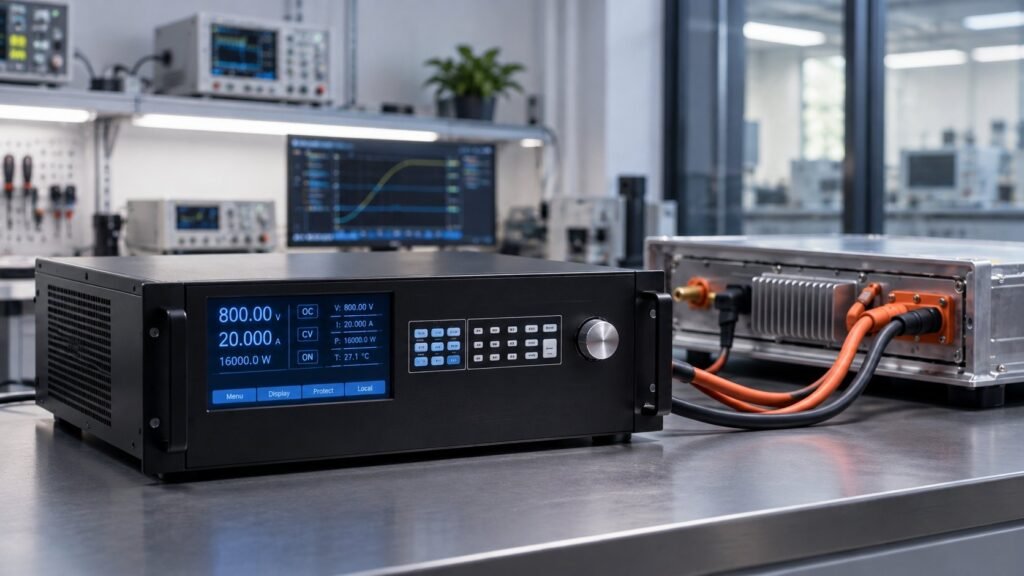
- 1. Set the operating point. Use 500 V DC, +35 A source current and −35 A sink current. The commanded reversal is 70 A across zero. Failure mode: an undersized current range clips the command and hides the true transition.
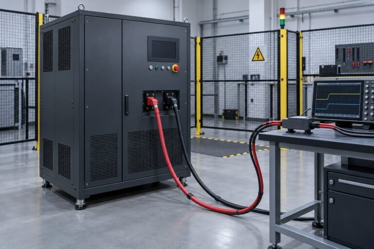
- 2. Fix the power path. Use 2.0 m total DC cable length, identical cable routing in both directions and remote sense enabled at the DUT terminals. Failure mode: changing cable inductance appears as simulator overshoot.
- 3. Configure the instruments. Trigger the oscilloscope on the current-command edge and use a second channel for the zero-current crossing. Use a 100 MHz bandwidth limit, a suitably rated differential voltage probe and current measurement at the DUT. Failure mode: an untriggered or bandwidth-limited trace gives false settling time.
- 4. Apply both reversals. Run +35 A to −35 A, then −35 A to +35 A after the waveform returns to steady state. Record peak overshoot, peak undershoot, transition time and settling time. Failure mode: one direction passes while the reverse transition excites control-loop oscillation.
- 5. Log protection status. Keep OVP, OCP, OPP, UVP and UCP armed, but record whether any protection operates. Failure mode: a protection trip can terminate the test before the worst voltage excursion is captured.
- 6. Store the acceptance trace. Report the N35500 result as 500 V, +35 A ↔ −35 A, 4.8 ms measured transition and 4.1 ms measured recovery, with cable length, sense state, bandwidth, peak error and protection status. Failure mode: a headline number without conditions cannot be reproduced.
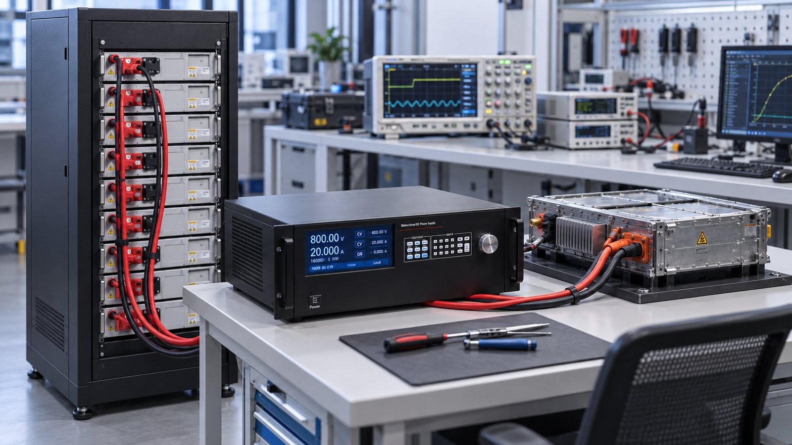
What failure does a fast current reversal expose?
The critical failure is DC-link overshoot or control-loop oscillation when the DUT reverses current faster than the simulator can change operating mode. The voltage can rise above the intended battery level during sink entry, then undershoot when the load is removed or the control loop changes direction.
Chroma explicitly warns that separate source-and-load systems can interrupt during charge/discharge switching. An integrated bidirectional system removes one hand-off point, but your trace still needs to prove that the DUT, cable path and simulator remain stable together.
- Fail the run if OVP, OCP, OPP, UVP or UCP operates unexpectedly.
- Flag any sustained ringing after the current zero crossing.
- Compare peak voltage error with the project limit; NEXUS lists ±5% full-scale dynamic overshoot as a reference.
- Report the first stable interval, not only the fastest crossing time.
- For BMS work, map each trace field to the applicable site:std.samr.gov.cn “gb/t 47136-2026” test requirement before automation.
Frequently asked questions about reversal testing
What does source-sink switching time measure?
Source-sink switching time measures the commanded current transition between positive and negative operation. Define the start and end points, such as −90% to +90% full scale, before comparing instruments.
Why does current reversal create voltage overshoot?
Cable inductance, DC-link energy and control-loop delay oppose the new current direction. If the DUT changes faster than the simulator responds, stored energy appears as a voltage peak or ringing.
Does remote sense change the measured result?
Yes. Remote sense moves the regulation point to the DUT terminals, so cable drop and inductive effects appear differently. Record the sense state and repeat the test with the same wiring.
Use the trace to specify your battery simulator
A credible bidirectional transient specification names the voltage, current, reversal amplitude, cable length, sense state, oscilloscope bandwidth, overshoot, settling time and protection status. Use the same fields for supplier comparisons and regression testing. Specify the trace, compare the result and review our battery simulator power supply range for the next bench build →