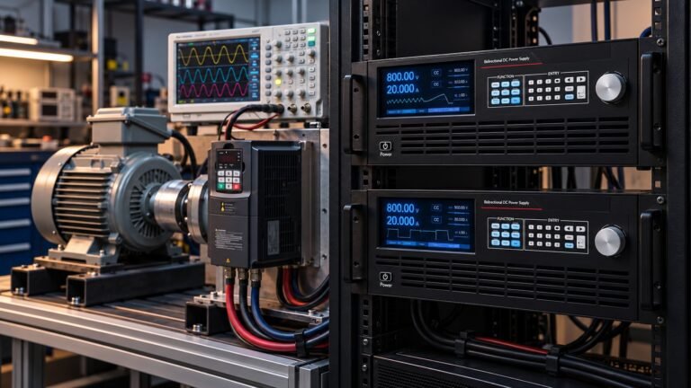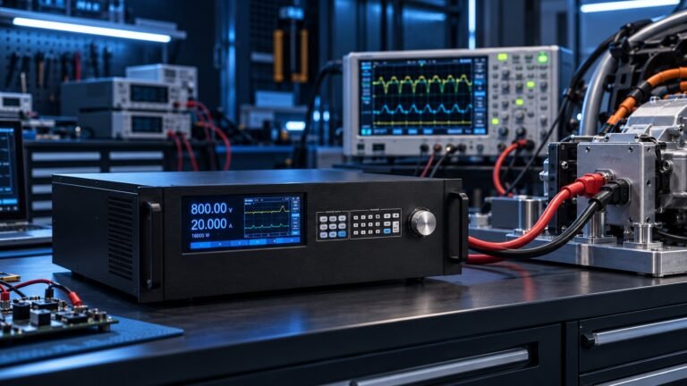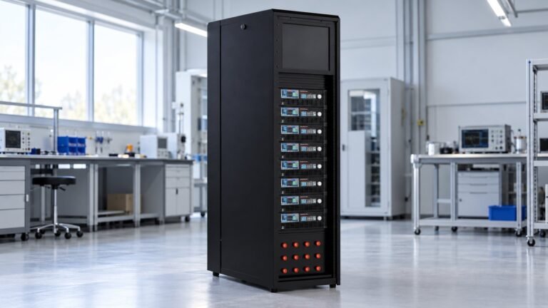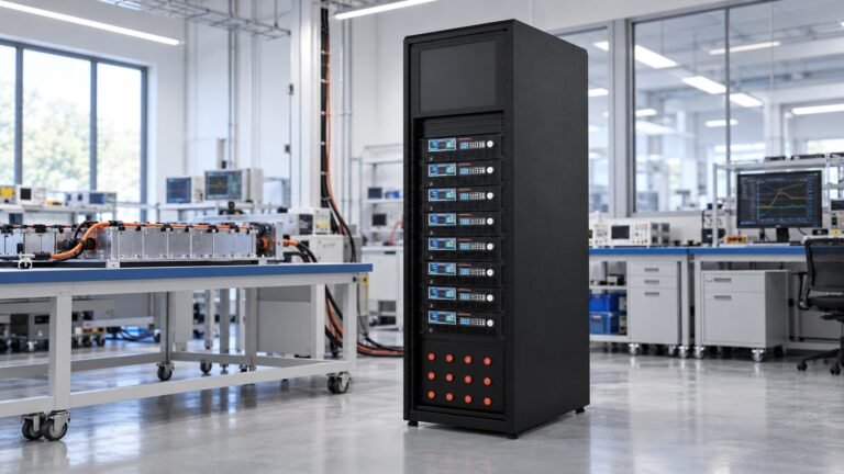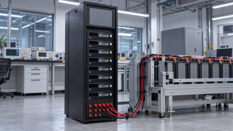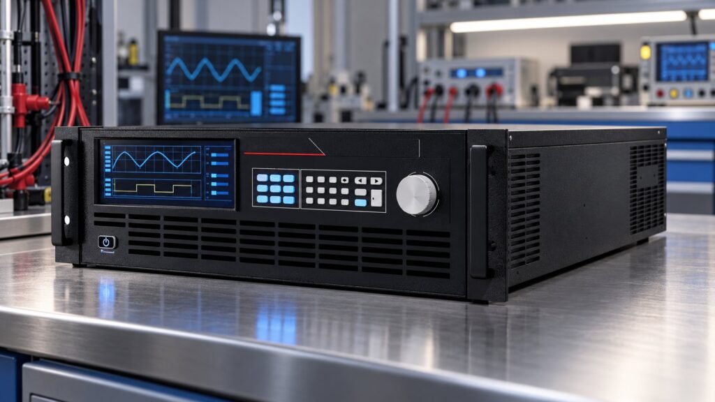
Choose a dc power system manufacturer by demanding proof that it owns the power stage and firmware, rates source and sink operation, and can pass your measured factory acceptance test (FAT). Verify voltage limits, current sharing, calibration traceability, protection response and field support before comparing price, catalogue breadth or delivery.
Current search results mix manufacturers, integrators and distributors. Thomasnet lists telecom plants from 24–250 VDC alongside EA systems rated from 80–1500 V, 3060 A and 30–90 kW. Gustav Klein describes engineer-to-order systems and lifecycle service. Intepro separates integration from manufacturing and lists systems reaching 2250 V. Ashkan, power supply engineer, uses those differences to define a measurable procurement check.
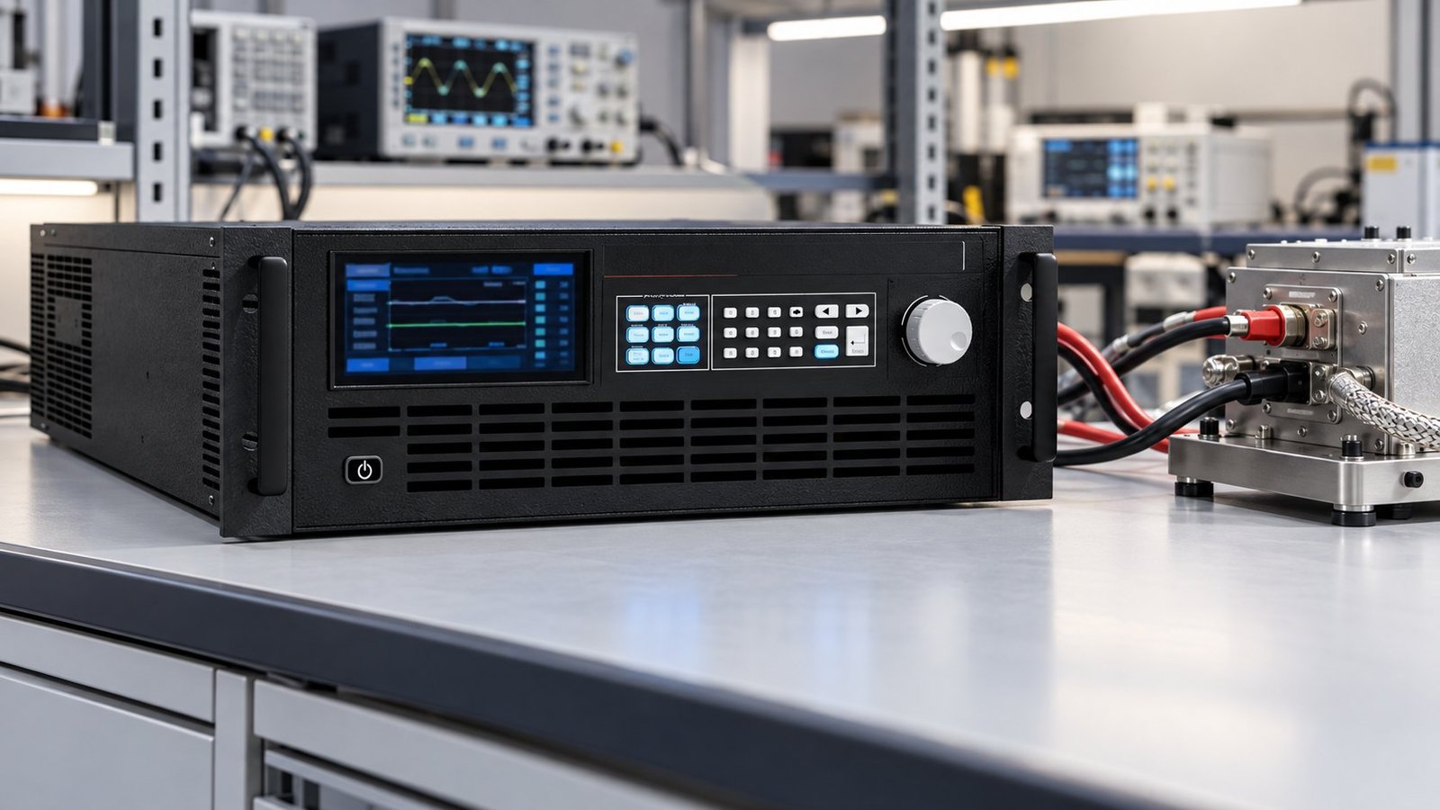
How do you separate a manufacturer, integrator and reseller?
A manufacturer owns the conversion hardware, control firmware and acceptance data. An integrator combines third-party equipment into a working test system. A reseller mainly selects and supplies equipment. Treat the distinction as a technical question, not a sales title.
| Supplier type | Evidence to request | Use when |
|---|---|---|
| Manufacturer | Power-stage drawings, firmware revision, serialised calibration records, protection limits and signed FAT data. | You need repeatable source/sink performance and long-term technical ownership. |
| Systems integrator | Bill of materials, interface responsibility matrix, integration FAT and named owners for each subsystem. | Your bench needs cabinets, interlocks, distribution, software and site commissioning. |
| Reseller or distributor | Original manufacturer, model identity, warranty route, calibration scope and replacement lead time. | The requirement is standard equipment with limited custom control. |
Thomasnet demonstrates why the label is insufficient. Its listings include distributors for 24 and 48 VDC telecom plants, turnkey integrators and manufacturers such as EA with 80–1500 V, 3060 A and 30–90 kW systems. Intepro’s separation of manufacturing and integration is a useful procurement distinction. Ask who is accountable when the source, sink, control loop or protection circuit fails.
What must a dc power system manufacturer own?
Your supplier should own the power stage and firmware, or identify the exact boundary where another company becomes responsible. For DC source sink systems, source and sink ratings must be stated separately. A single headline power figure does not prove bidirectional operation.
- Record the minimum operating voltage, maximum voltage, source current, sink current and continuous power in both directions.
- Identify the parallel-control method — master-slave, droop, digital current share or another defined scheme — and state the allowed share error.
- Require remote-sense behaviour, output discharge time, reverse-energy handling and the response to an open or shorted sense lead.
- Request calibration intervals, instrument IDs, uncertainty, traceability and as-found/as-left results.
- Name the firmware revision, communication interface, safety interlocks, spares strategy and field-support boundary.
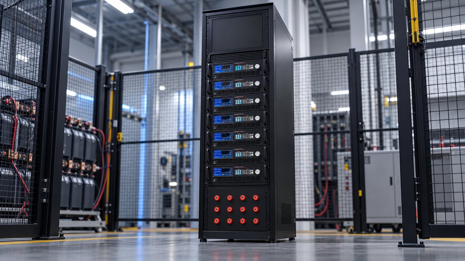
Use UltraPower’s N35500 platform as a comparison baseline. The range covers six classes from 360 V to 2250 V, reaches up to 42 kW in 3U, supports ±240 A per unit, reports 93% regeneration, responds within ≤5 ms and specifies 0.02% full-scale CV accuracy. These figures define questions for every bidirectional power system builder, not just a preferred product.
What should your FAT prove before shipment?
Require one redacted, signed FAT example rather than a blank test template. The record must show measured voltage, current, power, source-to-sink crossover time and pass/fail limits under stated conditions.
| FAT record | Evidence to require | Acceptance decision |
|---|---|---|
| Voltage and power hold | Setpoint, measured voltage, measured current, measured or calculated power, load condition and duration. | Pass only against the project’s voltage, current, power and accuracy limits. |
| Source-to-sink transition | Measured crossover time, direction change, bus excursion, current trace and controller state. | Pass only if the measured transition stays within the specified response and overshoot limits. |
| Calibration | Instrument serial numbers, calibration dates, traceability route, uncertainty and as-found/as-left results. | Reject unsupported claims such as calibrated without a record. |
| Protection and compliance | Actual protection thresholds, trip timing, reset behaviour and applicable test clauses. | Name IEC 61000-4-29:2026 Clause 6 where applicable, plus the project’s protection and calibration clauses. |
Give the supplier a concrete FAT line to complete: 800 V setpoint, 50 A command, measured voltage ___ V, measured current ___ A, measured power ___ kW, crossover ___ ms, CV limit ≤0.02% full scale, response limit ≤5 ms, and signed pass/fail status. A real FAT example must contain actual values, test conditions and limits. Do not accept nominal catalogue figures as measured evidence.
For photovoltaic, EV or grid-connected work, add only the standards in your project specification. That may include EN 50530, SAE requirements or IEC 61000-4-29:2026 Clause 6. Also record the actual overvoltage, overcurrent, reverse-energy, isolation and emergency-stop clauses used by the test plan.
Which failure modes should your acceptance test expose?
A credible high-voltage test system supplier tests abnormal energy flow, sensing faults and module imbalance. These cases reveal whether the controls are engineered as a system or merely assembled from catalogue parts.
- Drive the bus from an external DUT while the supply is sourcing. The failure mode is reverse energy entering the source path. Record whether the system transfers to sink mode, limits current or trips safely.
- Disconnect the remote-sense lead during a voltage hold. The failure mode is uncontrolled output correction or an unexpected overshoot. Verify the alarm, fallback control mode and shutdown threshold.
- Remove one parallel module from current share. The failure mode is a remaining module taking excess current. Record share error, overload response, isolation and whether the controller maintains a defined operating state.
- Interrupt the regeneration path during a sink event. The failure mode is DC-bus overvoltage. Verify the dump, grid-regeneration, contactor and interlock sequence against measured limits.
If your bench validates vehicle-to-grid power export, connect the acceptance plan to UL 9741 Testing for V2G Power Export. If regeneration is part of the AC interface, the next engineering reference is an ac dc regenerative converter commissioning guide.
See also: 12v dc power source
What should you still ask a dc power system manufacturer?
Does engineer-to-order mean the supplier manufactures the system?
No. Gustav Klein describes engineer-to-order capability, vertical integration and lifecycle service. Ask which assemblies, firmware and controls are made in-house, and which are purchased.
What proves that a source and sink are both rated?
Request separate continuous voltage, current and power ratings for sourcing and sinking. Confirm the ratings at your minimum operating voltage and during parallel operation.
What support should be included in the purchase?
Specify commissioning, remote diagnostics, spares, calibration, firmware control and response times for field faults. A lifecycle plan matters as much as the initial FAT.
How should you choose and proceed?
Choose the supplier that can show ownership, measured acceptance evidence and a defined response to reverse energy, sensing faults and current-share loss. Then compare architecture, lifecycle support and total test risk. If a lower-voltage auxiliary rail is part of your bench, compare the 12V DC power supply range and carry the same evidence rules into your RFQ →