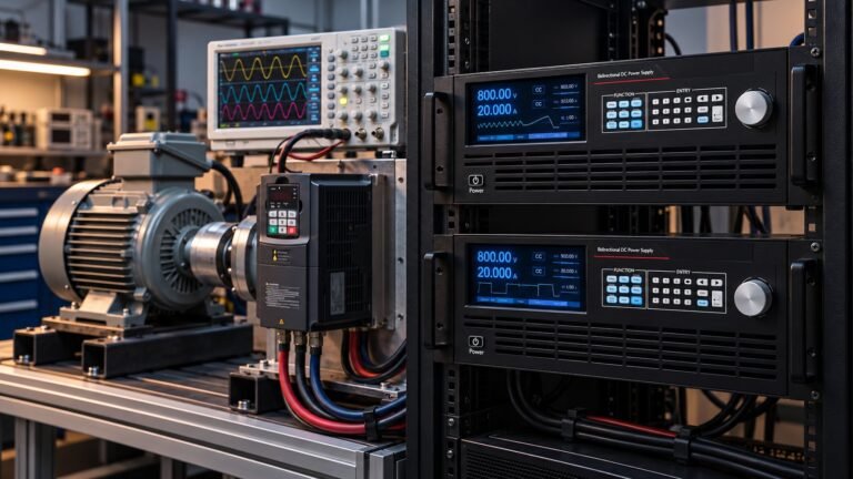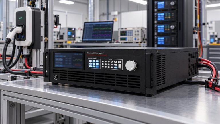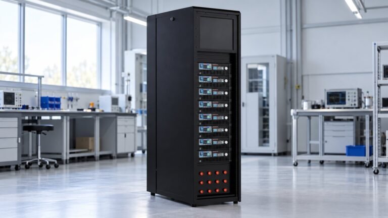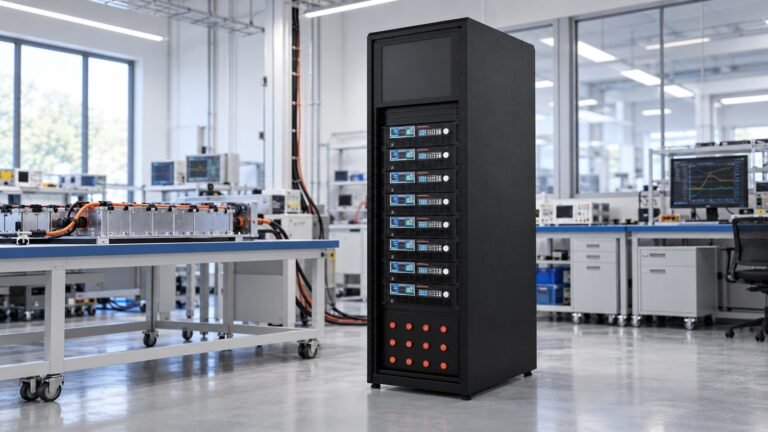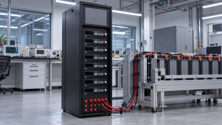
UL 9741 testing verifies whether EV power export equipment can control bidirectional power safely at its defined voltage boundary. Prepare a source-and-sink bench that emulates the vehicle DC bus, commands charge and export, removes the grid reference, disables export and opens contactors. Record disconnect-to-zero-power time in milliseconds and residual DC voltage after isolation.
On 14 September 2026, UL Solutions announced a V2G programme using UL 1741 Supplement SC. It can combine multipiece DER requirements with UL 9741. This post turns that certification direction into a practical bench plan for test engineers. It is written by Ashkan, power supply engineer.
What does UL 9741 testing cover?
UL 9741 testing covers off-board bidirectional equipment within a defined electrical and control boundary. UL Solutions’ 14 September 2026 announcement describes a V2G programme based on UL 1741 Supplement SC, with multipiece DER requirements able to work alongside UL 9741.
| UL 9741 boundary | Bench implication | Use when |
|---|---|---|
| Clause 1.1 — up to 1,000 Vac or 1,500 Vdc | Set the vehicle-side emulator inside the declared voltage class. | Your EV power export equipment operates within the off-board scope. |
| Clause 1.5 — export enable and disable | Command export, inhibit it, and verify the measured power response. | You need evidence that export control is functional. |
| Clause 1.6 — functions may be split across pieces | Document the interfaces between power conversion and interconnection equipment. | Your system uses separate conversion, control or grid-interface cabinets. |
The boundary is not a claim that a power supply alone certifies an EVSE. Your test bench supplies controlled electrical conditions. The EVSE, controls, contactors, protection and interconnection functions remain part of the product evaluation.
See also: 12v dc power supply
How should you build a V2G test bench?
A useful V2G test bench has four paths: vehicle-side DC emulation, grid-reference sensing, export control and time-correlated measurement. Keep the source and sink programmable so you can reproduce both charging and power-export states without changing the wiring.
Specify the source-and-sink equipment
Ultra’s N35500 platform covers 360 V to 2,250 V classes, bidirectional current to 240 A per unit and 14–420 kW. It provides dynamic response of ≤5 ms and regeneration efficiency of 93%. For a packaged option, compare your requirements with our EV charger test power supply range.
| Bench path | What to control | Use when |
|---|---|---|
| Vehicle-side DC emulator | Voltage, current direction, power level and transition timing. | You need to reproduce battery charge and discharge behaviour. |
| Grid-reference input | Presence, loss and restoration of the grid reference. | You are testing anti-backfeed and grid-loss response. |
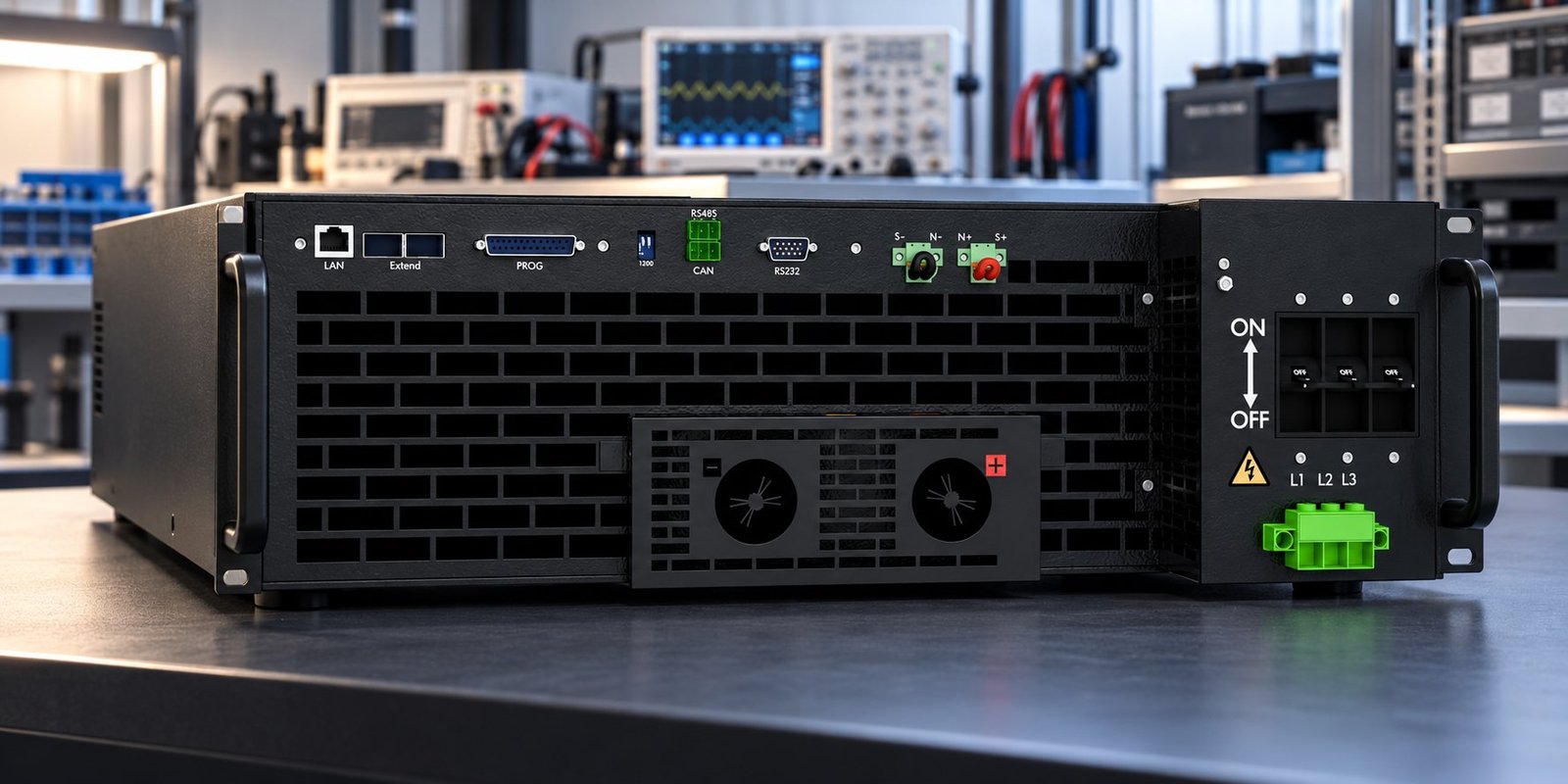
| Control and logging | LAN, RS232, RS485 or CAN with SCPI, Modbus-RTU or CANopen. | You need traceable commands, timestamps and fault evidence. |
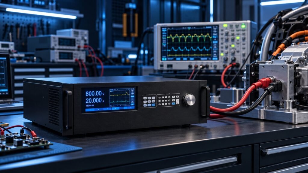
Use bidirectional and regenerative DC power supplies when the same unit must source and absorb DC power. Keep the measurement channel independent from the command channel. That separation helps you prove what the EVSE did rather than what the controller requested.
What sequence should bidirectional EV charger testing follow?
Run bidirectional EV charger testing as a controlled sequence from charge to export, then from export to isolation. The sequence below gives each event a measurable trigger and a named failure mode.
- 1. Establish vehicle-side DC emulation at the declared operating voltage. Confirm stable current and power before enabling export. Failure mode: unstable DC conditions. Trigger: voltage or current leaves the programmed operating window.
- 2. Command a source-to-sink transition from charging into export. Capture the power trace and command timestamp. Failure mode: uncontrolled transition. Trigger: output direction changes without the expected control event.
- 3. Issue the export-disable command under load. Confirm that power falls to zero and that the export path opens. Failure mode: failed export-disable command. Trigger: measurable export continues after the disable command.
- 4. Remove the grid reference while export is active. Confirm anti-backfeed protection and the abnormal-condition response. Failure mode: continued export after grid-reference loss. Trigger: non-zero export remains after the defined loss event.
- 5. Open the contactor and record the isolation result. Report disconnect-to-zero-power time in milliseconds and residual DC voltage after isolation. Failure mode: delayed or incomplete isolation. Trigger: power does not reach zero within the test limit or residual DC remains above the specified limit.
See also: 12v dc power source
Why does the EV source make testing harder?
Intertek’s 2026 FAQ explains that bidirectional EVSE testing becomes more demanding when the EV is also an energy source. Your plan must cover anti-backfeed protection, communications, abnormal-condition response and grid interaction together.
- Anti-backfeed protection — verify that grid-reference loss stops export.
- Communications — log the command, acknowledgement and measured electrical response.
- Abnormal-condition response — remove the reference or issue an invalid control event under a defined safe condition.
- Grid interaction — confirm the product does not continue exporting after the interconnection state changes.
- Energy recovery — if the bench returns energy to the AC side, review the ac dc regenerative converter commissioning requirements.
UL 9741 testing FAQ
Does a power supply alone certify an EVSE?
No. A power supply creates controlled source and sink conditions. The EVSE still requires evaluation of export control, protection, communications, contactors and interconnection behaviour.
What isolation result should you record?
Record disconnect-to-zero-power time in milliseconds and residual DC voltage after isolation. Compare both values with the limits in your certification test plan.
Can the power-conversion and interconnection functions be separate?
Yes. UL 9741 Clause 1.6 allows those functions to be split across multiple pieces. Test the interfaces as part of the complete equipment arrangement.
Prepare your bench before certification
A practical UL 9741 testing plan starts with a programmable DC source and sink, a controlled grid-reference event, export-disable verification and a timed isolation measurement. Specify the voltage class, current, power, response and communications interface before you select hardware. Review our 12 dc power supply options for a source-and-sink setup →