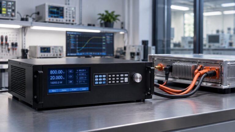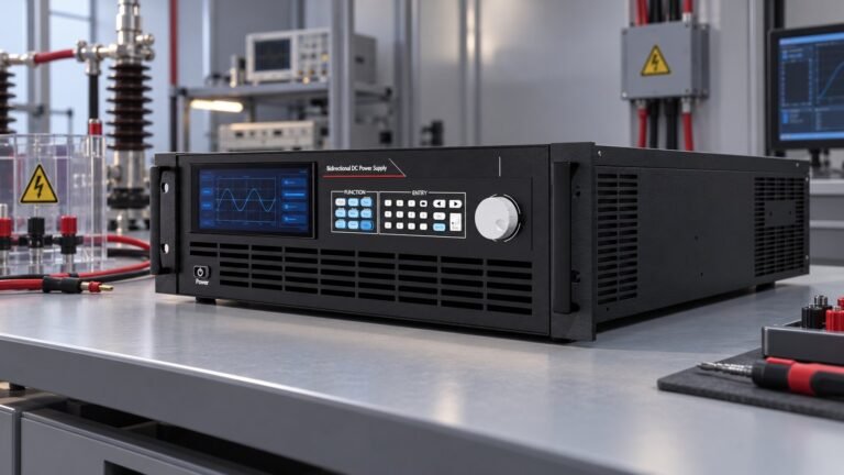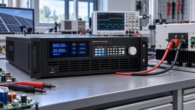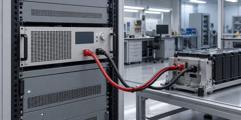
Bidirectional DC power supplies earn their place in a test rack when the device under test alternates between consuming and returning energy. The key decision is crossover behaviour. You need controlled voltage, current and power before, during and after the direction change.
For continuous charge discharge testing, specify the complete power path first. Your source mode must deliver the programmed profile. Your sink mode must absorb reverse current, return useful energy and protect the DUT. This workflow follows one real sequence from charge to discharge, then compares a single unit with a parallel cabinet.
How bidirectional DC power supplies cross modes
A practical sequence starts in source mode. The supply raises the DC bus to the requested voltage, then regulates the selected current or power limit. During battery charging, constant-current control can give way to constant-voltage control as the cell approaches its voltage ceiling. Your profile must keep voltage, current and power within their permitted limits at every step.
The direction changes when the DUT begins returning energy. The DC terminals now absorb current. A source and sink power supply therefore needs a controlled current reversal, not a simple output relay. The control system passes through a quadrant crossover while maintaining the requested operating boundary.
What to specify before the first run
Write down the expected bus voltage, maximum source current, maximum sink current and maximum regenerated power. Then define the allowed transition time. Ultra Power Systems sees representative response of ≤5 ms on suitable bidirectional platforms. That figure is useful only if the test fixture, cables and measurement loop support the same transient target.
- Set the source limit in volts, amps or kW before enabling the profile.
- Define the sink limit separately because returned current may exceed the charging current.
- Record the crossover voltage, current and recovery time on the DUT terminals.
- Check that protection thresholds sit outside the normal profile but inside the safe operating area.
Ultra Power Systems offers CC, CV, CP and CR modes across its bidirectional and regenerative DC power supplies. CC controls charge or discharge intensity. CV holds the bus at a set voltage. CP maintains an energy-flow target as voltage changes. CR represents a resistive load. These modes let you match the control law to a battery, converter, motor drive or electronic-load test.
See also: Megawatt Bidirectional DC Source Sink: Build by Paralleling
What the bench sees during transient recovery
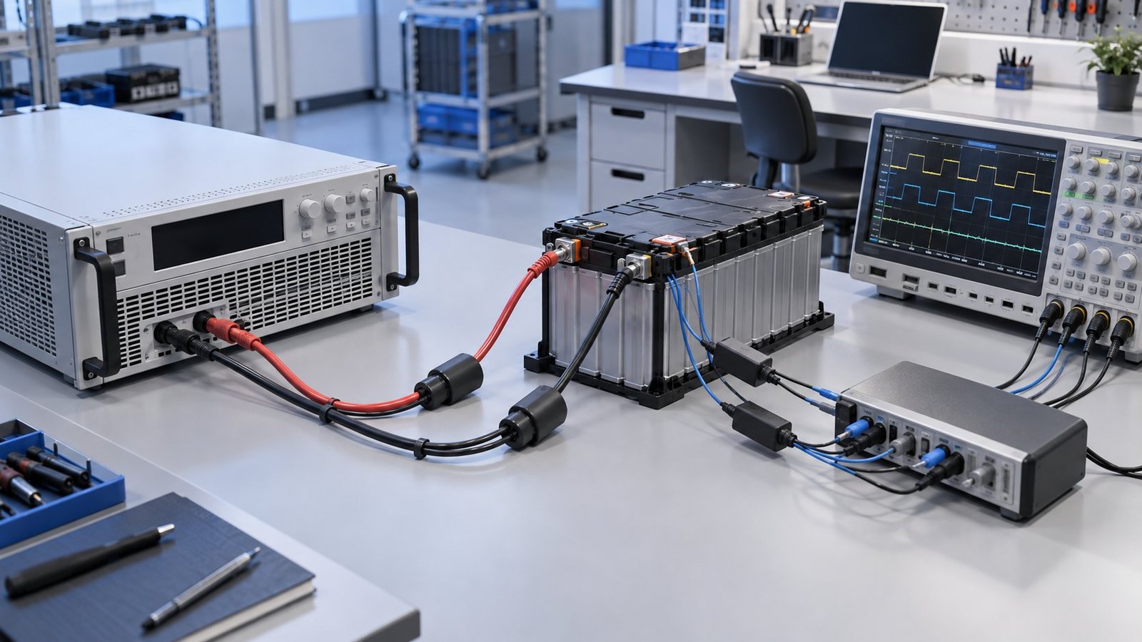
At crossover, the DUT does not wait for your software command to settle. A battery, inverter or motor drive can change current direction while the bus is already moving. Measure the terminal waveform at the DUT, not only the instrument display. Look for voltage overshoot, current hesitation and a temporary power gap.
A ≤5 ms response target gives you a useful reference for representative tests, but it does not remove the need for sensible ramps. Start with a moderate current slew. Confirm that the source-to-sink transition does not trip over-voltage or over-current protection. Then tighten the ramp until the measured waveform matches the product requirement.
Test and Measurement Tips describes a comparable 5–30 kW platform with automatic source-to-sink switching, custom waveforms and expansion to 1 MW. The practical lesson is to evaluate the complete sequence, not only the nameplate kW. A platform that changes direction automatically can reduce gaps between charge and discharge steps, while custom waveforms can reproduce drive, inverter or battery events.
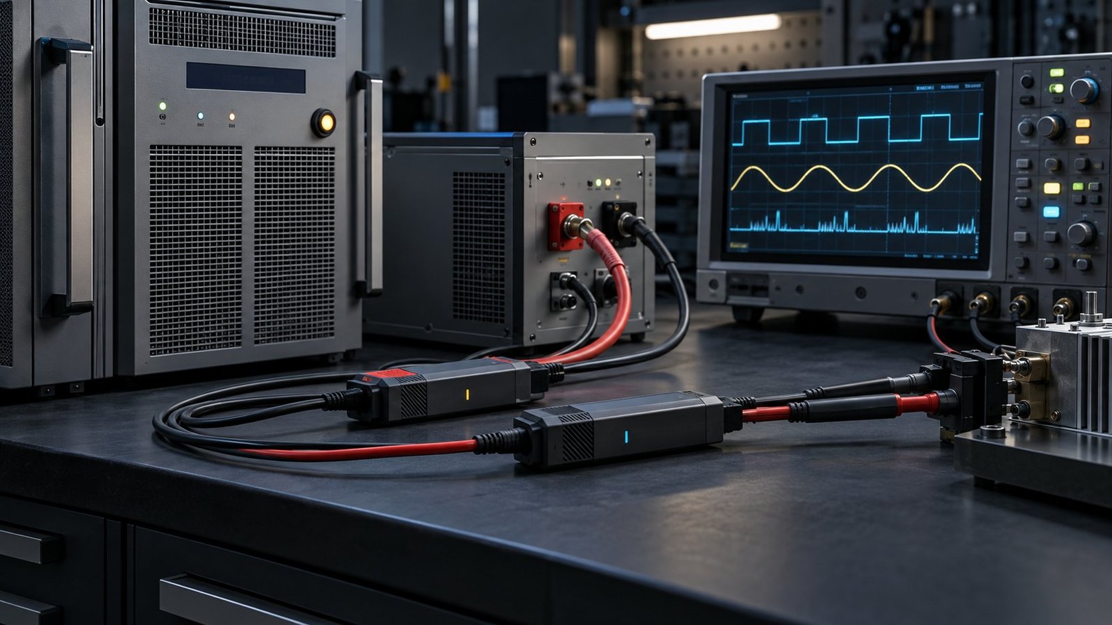
Use the same probe locations for every comparison. Record the DC-link voltage, DUT current and regenerated power at a fixed sample rate. For an inverter test, include the switching event that causes the reversal. For a battery test, include the point where the profile changes from charge to discharge. Consistent measurement makes a single unit and a parallel cabinet comparable.
See also: 800V DC Data Center Testing: New Bench Requirements
Regeneration, energy and cooling capacity
A regenerative DC power supply changes the facility calculation. In sink mode, absorbed energy can return to the grid instead of becoming heat in a resistor. GW Instek’s 21 August 2026 announcement reports up to 93% regeneration for its RBS Series, alongside new 20 kW and 30 kW 3U models and voltage classes reaching 2250 V.
Use a simple energy check before sizing cooling. Suppose your DUT returns 20 kW for 30 minutes during each discharge interval. That is 10 kWh of recovered DC energy. At 93% regeneration, about 9.3 kWh reaches the grid, while roughly 0.7 kWh remains as conversion loss. A resistive load would reject close to the full 10 kWh as heat.
The cooling difference is material. Ten kilowatt-hours released over 30 minutes equals an average 20 kW heat load. The regenerative case leaves approximately 1.4 kW of conversion heat over the same interval, before cabinet, cable and room losses. Check the actual efficiency curve at your voltage and power point. Do not size HVAC from the headline percentage alone.
Single unit or parallel cabinet
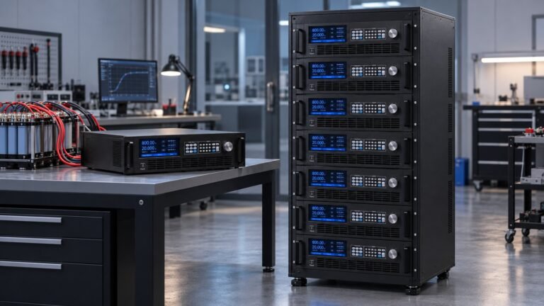
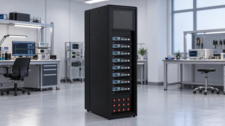
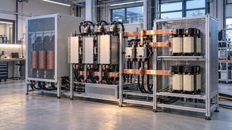
A single unit gives you a shorter power path and fewer current-sharing questions. GW Instek reports up to 30 kW from one 3U unit, with up to ten same-model units in master-slave parallel operation for a maximum 300 kW. Test and Measurement Tips describes scaling to 1 MW on a comparable platform. Choose a cabinet when the profile, voltage class or service plan requires expansion.
- Calculate source and sink energy separately for the full duty cycle.
- Apply the expected regeneration efficiency to returned energy.
- Estimate remaining heat from conversion, cables and cabinet losses.
- Compare the result with your rack cooling, breaker and grid-connection limits.
Build a repeatable continuous charge discharge test
A useful profile is short enough to debug and representative enough to expose crossover faults. For example, command a 750 V class system to source 40 A for 60 seconds, hold 30 kW maximum power, ramp to zero over 100 ms, then sink 35 A for 60 seconds. Repeat 100 cycles and log bus voltage, current, power and recovery time.
Keep the profile limits realistic. A 750 V bus at 40 A is 30 kW. At 35 A in sink mode, the returned power is 26.25 kW before losses. If your battery voltage moves between 600 V and 750 V, current or power control may be the better comparison because the energy flow changes with voltage.
Ultra Power Systems covers six voltage classes from 360 V to 2250 V. Select the class from the highest safe operating voltage, then check current at the lowest operating voltage. A 2250 V application can be power-limited long before it is voltage-limited. A 360 V application can reach its current limit first. The correct choice follows the whole waveform.
GW Instek reports sequence functions with up to 50 stored sequences and up to 20 configurable steps per sequence. You do not need to reproduce that architecture to build a sound test. Define each step by voltage, current, power, mode, duration, ramp and loop count. Keep the acceptance limits beside the profile so a failed crossover is immediately actionable.
FAQ: bidirectional DC power supplies
What is the main benefit of bidirectional DC power supplies?
They let one programmable platform source power to the DUT and sink returned power from it. That can reduce duplicated source and load hardware, cabling and waste heat.
How fast should source-to-sink crossover be?
Start with the DUT requirement. Ultra Power Systems uses representative response of ≤5 ms as a practical reference for suitable configurations, then verifies the result at the DUT terminals.
Does 93% regeneration mean 93% of test energy is recovered?
No. It describes the regeneration path under stated operating conditions. Calculate returned energy from measured sink power, duration and the efficiency available at your voltage and load point.
Choose the right bidirectional DC power supply
Your decision should follow the profile: voltage class, source current, sink current, crossover response, regenerated power and cabinet growth. For battery work, compare the sequence with the requirements on the Battery Cell Cycling Power Supply page. For a broader source-and-sink platform, review Ultra Power Systems’ Bidirectional & Regenerative DC Power Supply range, from 360 V to 2250 V classes. Specify the waveform and energy path first, then request a configuration →
A good acceptance test proves three things: the DUT sees the commanded voltage and current, crossover recovers within the required time, and returned energy does not exceed the sink or facility limits. That evidence tells you whether one unit is sufficient or a parallel cabinet is justified →