ISO 15118-23 DC testing is a communication conformance activity, not a complete EVSE qualification. ISO/PAS 15118-23:2026 defines an abstract test suite for EVCC and SECC behaviour against ISO 15118-20. It does not assess physical performance, robustness, reliability, or power-transfer capability.
Your 2026 DC EV charger testing plan therefore needs two coordinated paths. Use a protocol tester for ISO 15118-20 conformance. Use a controlled bidirectional DC source-and-sink stage for the electrical test. IEC 61851-23:2023 provides the physical EV supply equipment boundary, including system A bidirectional power-transfer requirements.
ISO 15118-23 DC testing defines the boundary
ISO/PAS 15118-23:2026 applies to a system under test that implements an electric-vehicle communication controller or supply-equipment communication controller. Its DC-specific cases come from ISO 15118-20. The test suite checks declared capabilities and observed behaviour. It uses an architecture inherited from ISO 15118-21.
The scope is communication from ISO/OSI layer 3 through layer 7 — network through application. That makes the document useful for message sequencing, capability handling, state changes and error responses. It does not judge the physical implementation behind those abstract service primitives.
The boundary is explicit. ISO/PAS 15118-23:2026 excludes performance, robustness and reliability assessment. It does not evaluate the surrounding environment of the protocol implementation. Power flow between the EVSE and vehicle is not a prerequisite for its abstract test cases.
- Protocol conformance: verify EVCC or SECC communication behaviour against ISO 15118-20.
- Electrical performance: verify DC voltage, current, ripple, transients and thermal response with laboratory power hardware.
- Safety and EVSE conformity: apply the relevant IEC 61851-23:2023 requirements and documented test methods.
- System correlation: time-align protocol events with measured DC voltage, current and contactor states.
Treat this distinction as a test-bench interface definition. A passing ATS result does not certify your EVSE. A stable DC output does not prove ISO 15118 conformance. Your evidence package needs both records, with each result attributed to the equipment and standard that produced it.
See also: solar array simulator
Build two test paths on one controlled bench
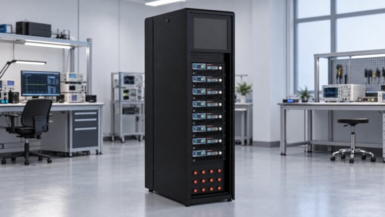
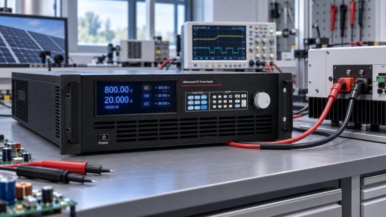
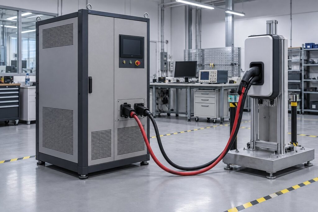
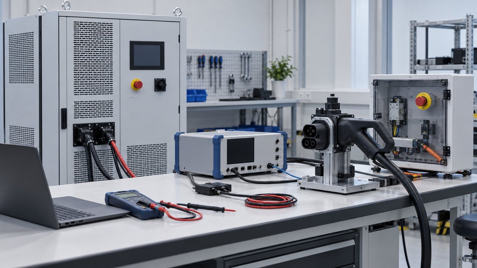
For bidirectional EVSE testing, place the communications path and power path under one test controller. The protocol tester drives the EVCC or SECC exchanges. The bidirectional DC stage establishes the electrical conditions. A shared timestamp lets you relate a requested current change to the measured ramp, contactor response and return-power event.
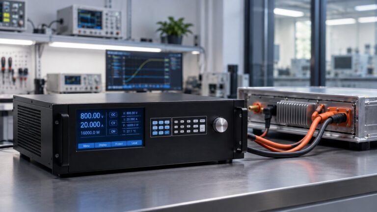
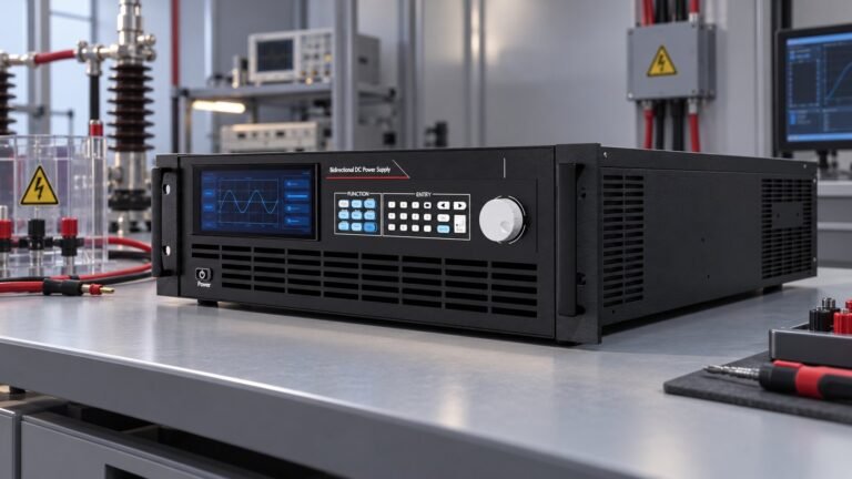
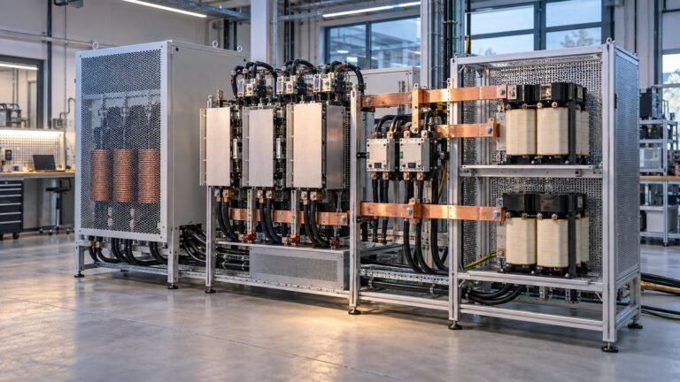
Your physical source-and-sink stage should cover both directions of the DC bus. In source mode, it emulates the EV battery or another controlled DC load line. In sink mode, it absorbs energy returned by the EVSE during reverse power transfer. Regenerative absorption keeps returned energy inside the test system instead of forcing a separate dissipative load.
Specify the operating envelope before selecting hardware. A 100 kW operating point requires about 278 A at 360 V and 66.7 A at 1,500 V. Those calculations show why voltage class changes cable size, contactor selection, enclosure design and measurement strategy. They are test points, not assumed product ratings.
We configure the source-and-sink stage around four practical controls: voltage-class selection, regenerative absorption, dynamic source-to-sink transitions and protection sequencing. Keep the protocol tester external. It should own the ISO 15118 message cases, while the power supply responds to defined setpoints and records the resulting physical behaviour.
Separate conformance evidence from performance evidence
Store protocol traces separately from electrical waveforms, then correlate them by test-case ID and timestamp. For each case, record commanded voltage, measured voltage, commanded current, measured current, DC ripple, transition time and protection state. Set acceptance limits from your product specification and applicable IEC requirements.
This structure prevents a common reporting error. A protocol tester can confirm that a controller sends or accepts the expected message sequence. It cannot confirm that a 750 V bus reaches its target within your required response time, that a 100 kW return event is absorbed, or that thermal limits remain controlled.
Choose the DC voltage class against IEC 61851-23
IEC 61851-23:2023 covers DC EV supply equipment transferring energy between the supply network and an EV. Its rated maximum is up to 1,000 V AC or 1,500 V DC on side A, with side B up to 1,500 V DC. The 1,500 V DC boundary matters when you define the EVSE test envelope and the insulation, switching and measurement architecture.
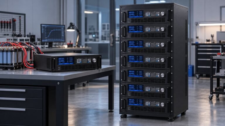
Ultra Power Systems offers bidirectional and regenerative DC power supplies in 360 V, 500 V, 750 V, 1,000 V, 1,500 V and 2,250 V classes. Select the lowest class that covers the intended operating range and transient margin. For an EVSE limited to 1,000 V DC, a 1,000 V class may simplify the bench. For a test envelope approaching the IEC side-B limit, specify the 1,500 V bidirectional DC power supply class.
The 2,250 V class is useful for equipment development beyond the IEC 61851-23:2023 1,500 V boundary. It does not extend the standard’s stated EVSE voltage scope. Mark that separation in your requirements document. A higher-rated laboratory source gives headroom for development; it does not make a 1,800 V EVSE conform to a 1,500 V requirement.
IEC 61851-23:2023 also revised electrical safety provisions, added conformity-test methods, and added requirements or information for thermal-management systems and bidirectional power-transfer control. It includes system A, system B and system C definitions. The published requirements for bidirectional power transfer apply to system A; reverse or bidirectional transfer for systems B and C is not specified in this edition.
Use the standard’s physical scope to drive bench hardware. Check DC isolation, discharge paths, pre-charge, contactor ratings, touch-current controls, cooling and artificial-load behaviour. For system A work, align the power stage with the bidirectional-control sequence. For other system types, document which behaviours are engineering tests rather than claims of IEC 61851-23 conformity.
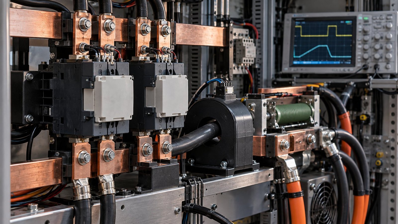
See also: ultra power solutions
Sequence protection before you automate cases
Protection sequencing is where a clean protocol trace can meet a failed physical test. Define the order for interlock validation, DC bus discharge, pre-charge, main contactor closure, voltage enable and current release. On shutdown, reverse the sequence deliberately. Your controller should inhibit source or sink operation if any interlock, insulation monitor or cooling permissive is missing.
Test the transition rather than only the steady state. Start with a controlled source at 360 V or 750 V, apply a defined current request, then command a sink transition. Capture voltage deviation, current crossover, contactor state and absorbed energy. Repeat at the upper operating point. At 1,500 V, even a 100 kW return event reaches only 66.7 A, but the stored and transferred energy still demands controlled switching and discharge.
- Run the external protocol tester through the selected ISO 15118-20 DC case.
- Translate the case’s physical stimulus into a voltage, current or source-to-sink setpoint.
- Apply the stimulus only after interlocks, pre-charge and thermal permissives are valid.
- Log the electrical response with millisecond timestamps and preserve the protocol trace.
- Classify the result as protocol, physical, safety or combined evidence.
Keep separate limits for voltage accuracy, current accuracy, ripple, efficiency, transition response and thermal rise. For example, do not use a protocol timeout as a substitute for a 100 ms electrical transition limit. Define the measurement bandwidth and sampling rate before the test. Otherwise, two benches can report different ripple or response results from the same DUT.
Use the external tester as the protocol authority
A DC power supply provides the physical source-and-sink function. It does not replace ISO 15118 protocol equipment, implement an EVCC or SECC ATS, or certify an EVSE. Keep message generation, certificate handling and conformance verdicts in the communications system. Let the power stage execute controlled electrical conditions and expose measurement data to the automation layer.
FAQ: ISO 15118-23 DC testing
Does ISO/PAS 15118-23:2026 require power flow?
No. ISO/PAS 15118-23:2026 states that power flow between the EVSE and EV is not a prerequisite for its abstract communication test cases.
Can an ATS result prove physical EVSE performance?
No. The document excludes performance, robustness and reliability assessment. Use physical measurements and the relevant IEC 61851-23:2023 work for those questions.
Which voltage class fits a 1,500 V DC boundary?
Choose a 1,500 V class when your EVSE test envelope reaches the IEC 61851-23:2023 side-A or side-B limit. A 2,250 V class supports development above that boundary, but does not change the standard’s scope.
Conclusion: specify the complete test bench
Start your requirements with the boundary: ISO/PAS 15118-23:2026 tests communication behaviour, while IEC 61851-23:2023 governs the relevant DC EVSE and system A bidirectional power-transfer requirements. Then size the voltage class, regenerative absorption, transition control and protection sequence around your real DC envelope. For a coordinated physical source-and-sink stage, review the EV charger and BOBC test power supply →