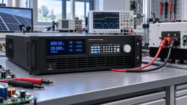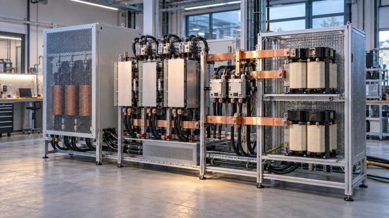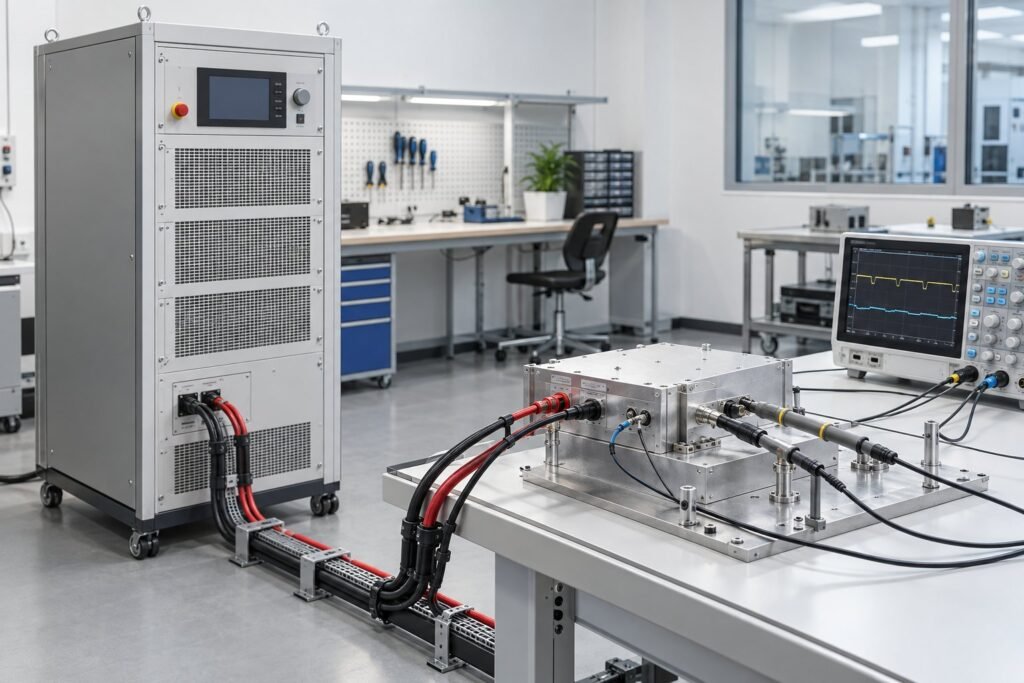
An IEC 61000-4-29 DC power supply must reproduce controlled DC-input disturbances, not just deliver a stable voltage. The July 30, 2026 revision changes how you specify the generator, interruption path, current margin, and evidence collected during testing.
This guide takes a purchasing view. It translates the revised requirements into checks for your test bench, then compares the 360 V, 500 V, and 750 V Ultra Power Systems classes. Ask engineering to validate every supply claim against actual test data before you release a compliance procedure.
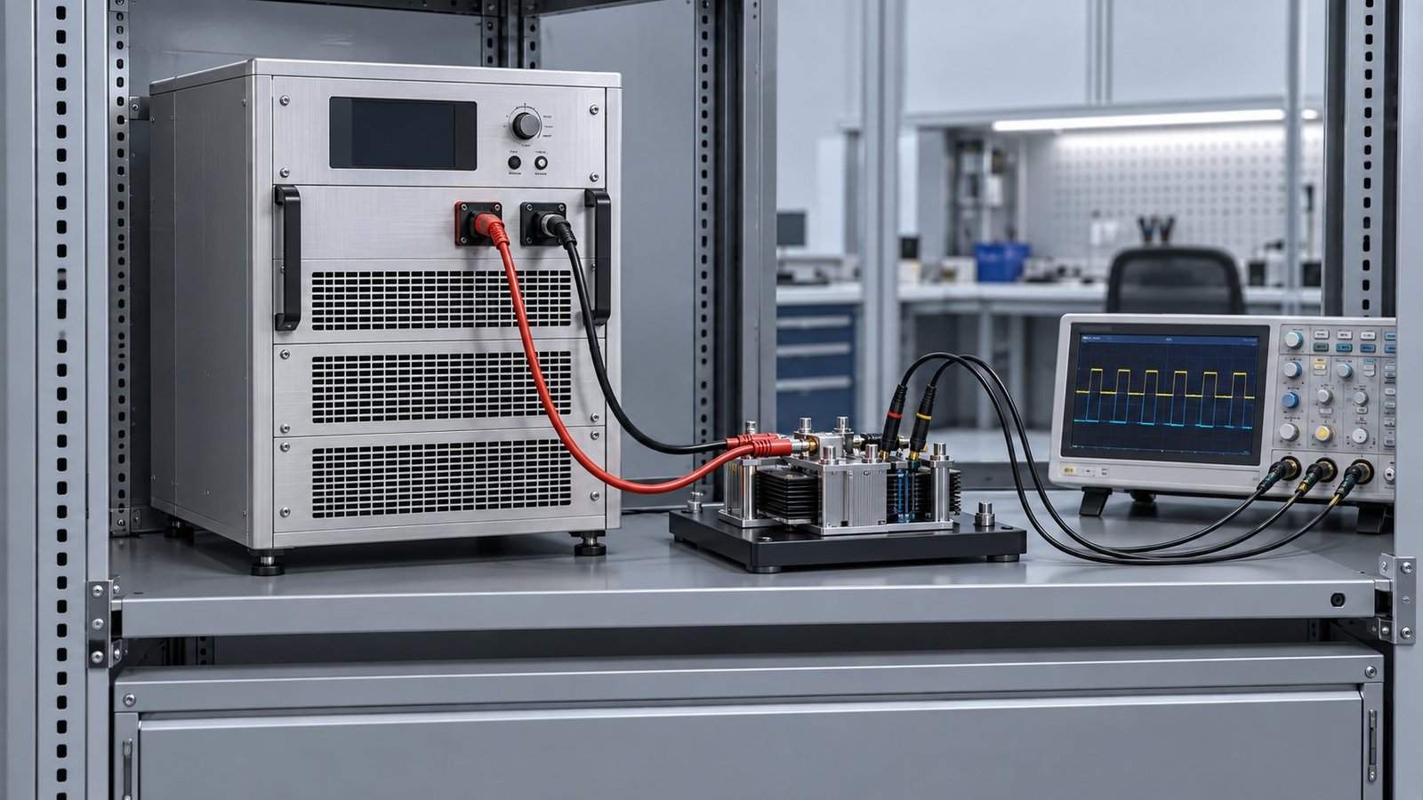
Why the 2026 revision changes supply selection
IEC 61000-4-29:2026 is Edition 2.0, published on July 30, 2026. It replaces the 2000 edition. The IEC 61000-4-29 Redline version identifies changes across DC-input voltage dips, short interruptions, voltage variations, generator requirements, test setup, procedures, and reporting.
For a lab manager, the revision moves the purchasing question away from nominal voltage alone. You need a generator that can create the specified disturbance at the equipment under test, maintain the required current path, and document what happened at the EUT terminals.
The revision also raises generator voltage capability and clarifies duration tolerances. It adds detail around low-impedance interruption current limits, inrush verification, and the DC environment. Intepro Systems’ practical interpretation highlights four supply characteristics that deserve attention before you approve a quotation.
- Voltage transitions with edges between 0.5 and 50 microseconds.
- Generator output up to 120% of the maximum test voltage.
- At least 20% steady-state current margin above the EUT requirement.
- Source and sink capability for peak inrush, with a genuine high-impedance interruption path.
These figures describe generator capability. They do not select product-specific pass or fail levels. IEC 61000-4-29 leaves severity selection to the relevant product committee, so your test plan must identify the applicable levels separately.
Specify an IEC 61000-4-29 DC power supply
Start with the voltage and current envelope
For DC voltage dip testing, calculate the highest generator output before choosing a supply class. Use the maximum test voltage and include the 120% generator capability stated in the practical interpretation. A 300 V test ceiling, for example, requires 360 V of generator headroom. That calculation can change the correct class.
Current margin needs the same discipline. Measure the EUT’s steady-state draw at the relevant voltage, then add at least 20%. Do not size only from the nameplate rating. Loads with input capacitors, active front ends, contactors, or DC-link converters can demand a short inrush pulse that exceeds their operating current.
Treat the interruption path as a power function
A programmable DC test supply should source the commanded voltage and sink energy returned by the EUT. It should also create a real high-impedance interruption. Programming the output to 0 V is not equivalent to disconnecting the source, because the EUT may back-feed the gap.
Intepro Systems describes a single programmable DC supply as an accepted generator architecture when it meets the required edge, current, source, sink, and interruption conditions. In practice, you should verify the exact switching behaviour with probes and current measurement rather than accepting an architecture diagram as evidence.
Remote control matters when the test sequence includes several voltage levels and interruption durations. Record command timing, measured terminal timing, repeatability, and the relationship between the software sequence and the captured waveform. Your control interface is part of the test system.
See also: Programmable DC Source Sink: The Quadrant Map
Match 360 V, 500 V, and 750 V classes
Ultra Power Systems supplies bidirectional and regenerative DC power supplies in 360 V to 2250 V classes. For this standard, the useful comparison is not simply the highest nominal voltage. Check whether the class still has the required headroom after applying the 120% generator requirement, then check current, sink energy, isolation, and response at the EUT.
The 360 V bidirectional DC power supplies can support relevant test ranges when the maximum required generator voltage remains within 360 V. A 360 V class is therefore suitable for test plans whose maximum voltage stays at or below 300 V when the 120% allowance must be demonstrated. Engineering should confirm the actual response at that operating point.
The 500 V bidirectional DC power supplies provide additional voltage headroom for higher-voltage DC links and EUT input stages. Apply the same calculation. A 500 V class can cover a maximum test voltage of 416.7 V only if the complete generator specification, waveform response, current margin, and interruption method are verified.
The 750 V bidirectional DC power supplies address higher DC environments where a 120% requirement would otherwise exceed a lower class. Do not treat the class name as proof of compliance. Confirm output capability, sink behaviour, isolation, and measured response for the exact test profile.
See also: How to Read Bidirectional DC Power Supply Model Numbers
Validate the waveform and the evidence
At Ultra Power Systems, we treat measured response, sink behaviour, remote control, and isolation behaviour as separate acceptance checks. A supply may meet its static voltage rating and still fail to reproduce the disturbance at the EUT terminals.
- Measure the commanded voltage edge and the voltage seen by the EUT. Check the transition against the 0.5 to 50 microsecond range.
- Record source current during recovery and sink current when the EUT returns energy. Include the peak inrush event in the capture.
- Compare the programmed sequence with measured timing. Confirm duration tolerances in absolute seconds, not inferred mains cycles.
- Verify that interruption mode creates the required high-impedance state. Check for EUT back-feed during the gap.
- Store voltage, current, control commands, equipment state, and test conditions in the report.
The IEC 61000-4-29 Redline version addresses setup, procedures, and reporting, so your record should show more than a pass label. Capture the actual waveform, current path, EUT operating condition, and recovery result. Ask engineering to validate each claim against the test data from the intended supply, cabling, probes, and load.
The standard excludes ripple on the DC port. Ripple testing belongs to IEC 61000-4-17. Keep that boundary clear in your procurement specification. An IEC 61000-4-29 DC power supply does not automatically cover ripple performance, product-specific severity selection, or certification by itself.
FAQ: IEC 61000-4-29 DC power supply
Does IEC 61000-4-29 define pass or fail levels?
No. Product committees select the applicable severity levels. The standard defines the disturbance and generator framework, not every product’s acceptance limit.
Can one programmable supply act as the generator?
Yes, a single programmable supply is an accepted architecture when it meets the required voltage edge, output capability, current margin, source and sink behaviour, and interruption conditions.
Does setting the output to 0 V create an interruption?
Not necessarily. A genuine interruption requires a high-impedance path that prevents the EUT from back-feeding the source during the gap.
Choose the supply from measured evidence
The 2026 revision makes generator capability a central purchasing decision. Start with maximum voltage, apply the 120% headroom requirement, add 20% steady-state current margin, then verify edge speed, inrush source and sink behaviour, interruption impedance, remote control, and isolation at the EUT. Use the DC power-supply specification glossary to align those terms before requesting a quotation. →