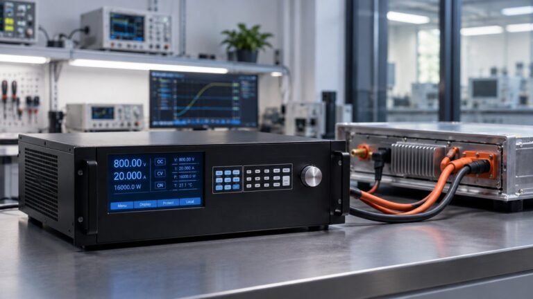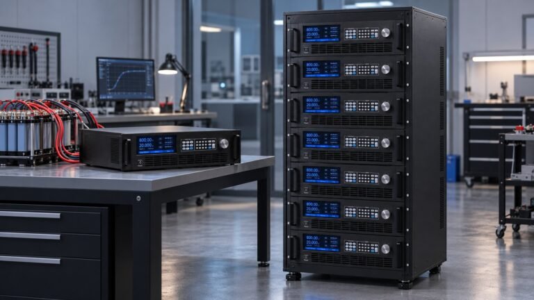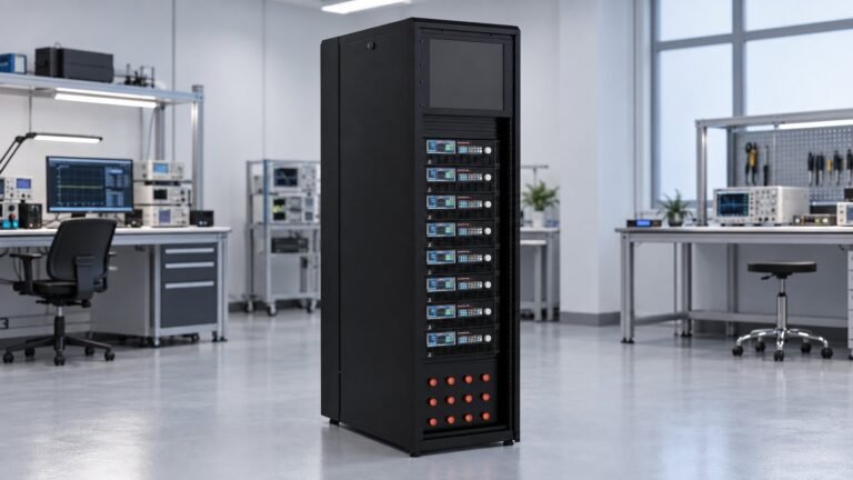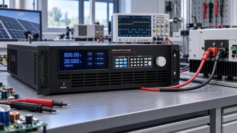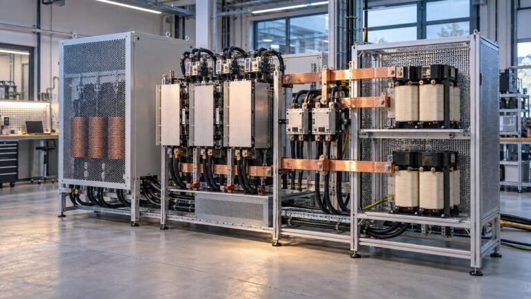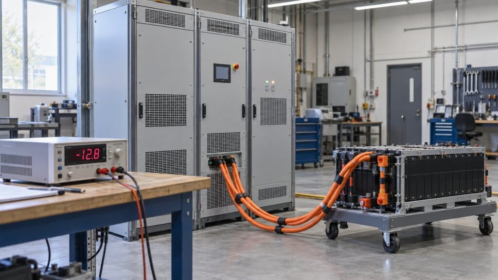
A programmable DC source sink is almost always a two-quadrant instrument, not a four-quadrant one. It holds output polarity fixed and reverses only the direction of current. That single distinction decides whether the unit on your quote sheet can do what your battery, EV or inverter test plan needs — and datasheets blur it constantly.
This post does one job: it draws the line between the terms. Mechanical definition first, then the quadrant map, then our own crossover measurements at zero current. We skip product comparisons and model-number decoding entirely.
Sourcing or sinking — the mechanical test
Rohde & Schwarz put it in one line: if current flows into the positive voltage terminal, the supply is acting as an electronic load. It is sinking, not sourcing. You see it on the front panel as a negative current reading. R&S also note that this happens the moment the externally applied voltage exceeds the set nominal voltage, and that two- and four-quadrant instruments switch between modes automatically — no command, no relay, no operator action.
So a sinking current DC power supply is not a separate product category. It is the same output stage running with the current arrow reversed. ActionPower frames the identical idea with power sign: P = V × I, source when P is positive, sink when P is negative.

See also: Regenerative DC Electronic Load for High-Power Testing
The four quadrants, in plain terms
ActionPower’s Powerpedia entry sets the plane out with voltage on one axis and current on the other. Read it this way:
- QI — positive V, positive I. Forward source. A standard unipolar supply never leaves here.
- QII — negative V, positive I. Sink. Power is negative; the instrument absorbs energy under reversed voltage polarity.
- QIII — negative V, negative I. Reverse source. Energy still flows out, polarity inverted. ActionPower cites op-amp rails and motor-driver test as the use case.
- QIV — positive V, negative I. Regenerative sink. Polarity stays positive, current reverses. This is where your battery charging and inverter braking energy lands.
Now the point buyers miss. Battery, EV and grid work needs QI and QIV only. The DUT never changes polarity — a 400 V pack is +400 V whether you charge or discharge it. So the instrument you want is a two-quadrant bidirectional DC source and sink, and paying for QII and QIII buys you hardware your test plan will never enter.
See also: How to Read Bidirectional DC Power Supply Model Numbers
Two-quadrant vs four-quadrant power supply: when polarity reversal is real
The two-quadrant vs four-quadrant power supply question has a short answer: specify four-quadrant only if your DUT genuinely sees negative voltage at the terminals. In fifteen years of quoting we see three cases that qualify.
- Bipolar analogue work — ±15 V or ±30 V rails swept across the 0 V crossing for op-amps and mixed-signal front ends. R&S call this a bipolar supply operating in quadrants 1 and 3.
- Motor and coil drive where the winding is driven both directions from one pair of terminals, and braking current returns under the opposite polarity.
- Reverse-polarity abuse testing — deliberately applying negative voltage to a battery management system or charger input to prove the protection trips.
Everything else is two-quadrant. If you are testing a 800 V EV pack, a 1500 V string inverter or a PCS, a source sink system fixed at positive polarity covers the whole profile. Rule the fourth quadrant in on evidence, not on the datasheet sounding better.
Output impedance — the spec that goes with it
R&S flag a related capability worth asking about: adjustable output impedance. Real batteries raise their internal resistance as they discharge, and a supply with a fixed near-zero impedance will not reproduce that sag. R&S list it on the NGL200, NGM200 and NGU201. Ask for it by name when your programmable DC source sink has to stand in for a cell rather than merely feed one.
Crossover at zero current — what we measure on our own units
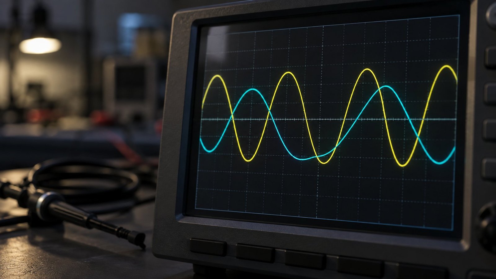
This is the specification nobody publishes and every battery lab needs. Crossover is what the output does as current passes through zero, from charge to discharge. Our numbers, measured at the terminals with a 500 kHz current probe:
- Transition time charge → discharge: < 2 ms at full-scale current, typical 1.2 ms on the 750 V class.
- Dead band at zero current: none. Control is continuous through 0 A; there is no ±1 % window where the loop stops regulating.
- Relay switching: none in the power path. Crossover is handled by the converter’s control loop, not by contactors. Output relays are used for isolation at shutdown only, so crossover does not consume mechanical life.
- Regeneration efficiency back to the grid: 93–95 % measured at 50–100 % load, falling to about 88 % below 20 % load.
- Two-quadrant across the range: all classes from 360 V to 2250 V are two-quadrant source-sink. None are four-quadrant; we do not offer polarity reversal in this range.
Voltage recovery at the step is under 1 % of setpoint at 200 A, settling inside 5 ms. Those figures matter more than peak power on most battery quotes we handle.
A bench case where a dead band bites
A customer ran a 100 Ah LFP module on a competitor cabinet with a ±0.5 A dead band. The profile was a CC step: charge at 50 A, then discharge at 50 A with no rest. Inside the dead band the control loop idled for roughly 40 ms. The pack sat at open-circuit while the coulomb counter kept integrating, so each cycle logged about 0.5 mAh of phantom charge. Over 600 cycles the capacity-fade curve drifted by 1.8 % — enough to fail an internal acceptance limit that was never really about the cells. Continuous crossover removed it.
What to write on the specification
Four lines settle it with any vendor. Ask for them in writing, not over a call.
- “Two-quadrant (QI/QIV) or four-quadrant (QI–QIV)?” — force the quadrant numbers, not the word bidirectional.
- “Dead band at 0 A, in amps or % of full scale?” — a number, or a written statement that control is continuous.
- “Charge-to-discharge transition time, at what current?”
- “Relays or contactors in the power path during crossover — yes or no?”
If a vendor answers the first question with “bidirectional”, you have learned nothing. The word covers both architectures. Our datasheets and downloads state the quadrant pair explicitly for every class.
FAQ
Is a bidirectional supply the same as a four-quadrant supply?
No. Bidirectional describes current direction. Four-quadrant adds voltage polarity reversal. Most bidirectional units, including every class we build from 360 V to 2250 V, are two-quadrant.
How do I confirm the unit is sinking?
Read the current sign. Per R&S, current flowing into the positive terminal shows as a negative reading. Apply an external voltage above the setpoint and the meter goes negative on its own.
Does a dead band always matter?
Only where the profile crosses zero under closed-loop control — battery cycling, drive-cycle replay, HIL. For a steady discharge or a steady charge that never reverses, it never shows up.
Do I need four quadrants for motor drive testing?
Usually not on the DC bus. The bus stays positive; regenerative braking returns current in QIV. You need four quadrants only when the DUT terminals themselves see negative voltage.
Getting the vocabulary onto your purchase order
Fix the terms before you compare prices. Source and sink describe current direction at fixed polarity; quadrants describe polarity as well. Our spec glossary for bidirectional DC power supplies defines each term against the quadrant it maps to, so you can check a competing datasheet in a minute. From there, the bidirectional and regenerative DC range lists crossover and regeneration figures per class, and request a quote if you want the measured trace for your voltage class →