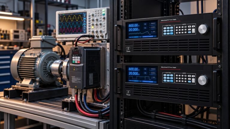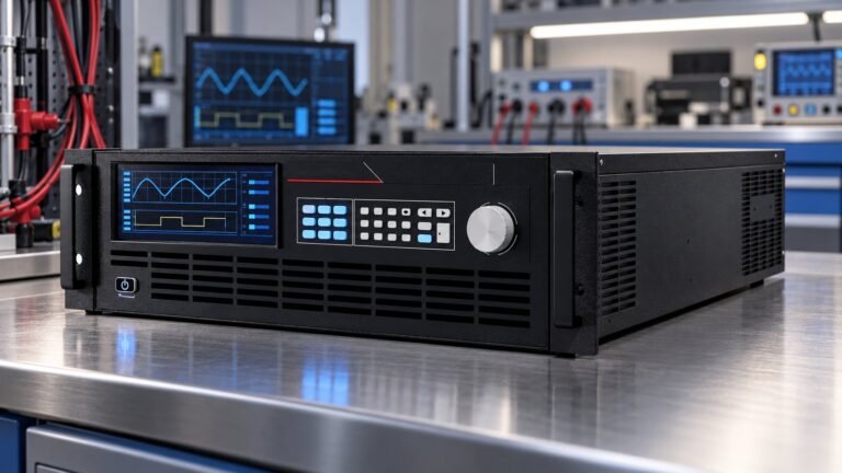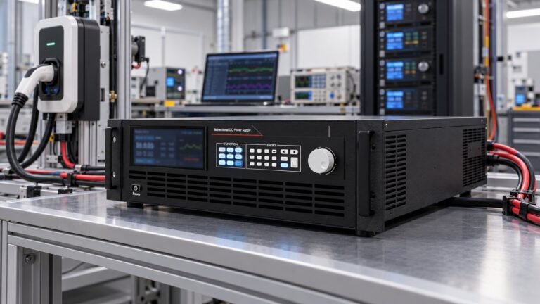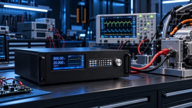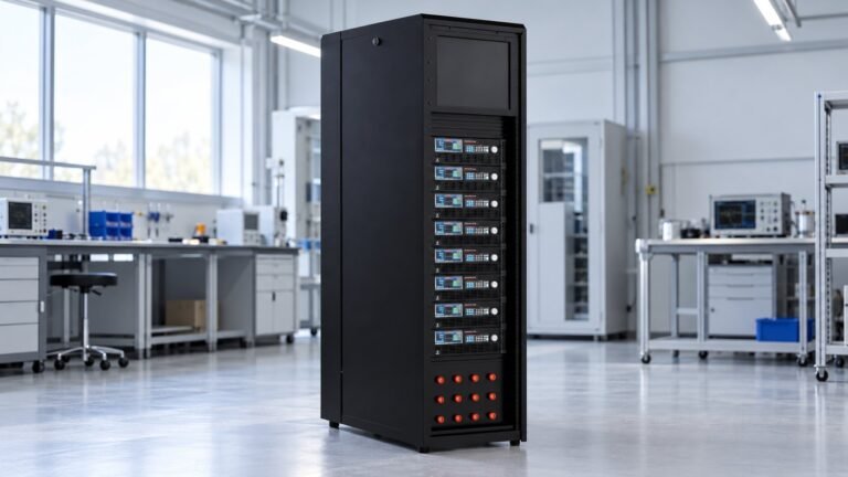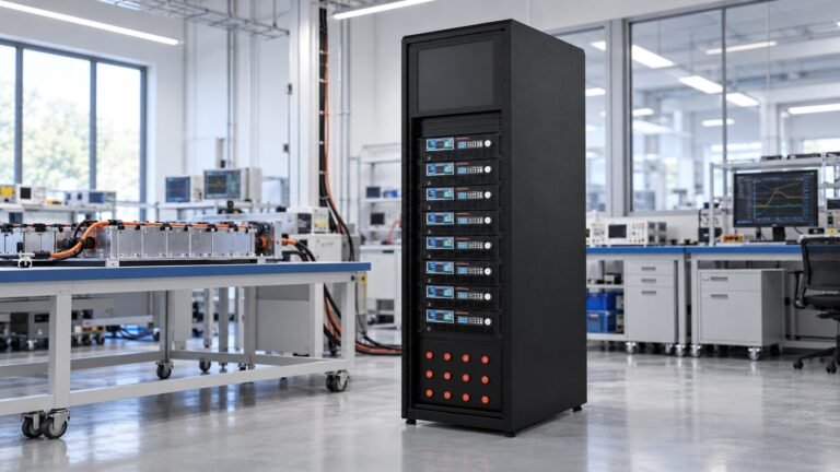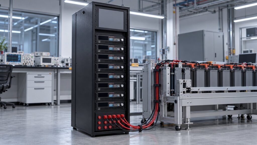
The UN R100 overcurrent test is a controlled REESS test: set 20 ± 10 °C, use a mid-range state of charge, agree the maximum voltage and overcurrent level, then ramp from the highest normal charge current to that level in 5 seconds. End when protection trips or temperature stabilises, and retain the measured overshoot and trigger.
That sequence follows Annex 9J paragraphs 2(a)–(c) and 4(b)–(c) in UN Regulation No 100 – 2026/1695. GRSP/2026/25, dated 14 October 2026, proposes treating Annex 9J as reserved for formal review in December. The proposal is not adopted law. The practical gap is the programmable source profile, measurements and cutoff logic.
What does the UN R100 overcurrent test require?
The UN R100 overcurrent test starts with three controlled conditions and ends with a defined protection event. Annex 9J paragraphs 2(a)–(c) require an ambient condition of 20 ± 10 °C, a mid-range REESS state of charge, and an agreed maximum voltage and overcurrent level.
Paragraph 4(b) then raises current from the highest normal charge current to the agreed overcurrent level over 5 seconds. Paragraph 4(c) ends the test when REESS overcurrent protection trips or the temperature stabilises. The UNECE R100 Battery Testing | ISO 17025 Lab page helps identify the test context, but your change-controlled method must define the source profile and evidence.
| Control point | Required condition | Evidence to retain |
|---|---|---|
| Ambient condition | 20 ± 10 °C | Measured temperature and timestamp |
| REESS state of charge | Mid-range starting SOC | SOC value before the ramp |
| Voltage and current limits | Agreed maximum voltage and overcurrent level | Approved test sheet revision |
| Current ramp | Highest normal charge current to overcurrent level in 5 seconds | Setpoint and measured-current trace |
| End condition | Protection trip or temperature stabilisation | Trip trigger, temperature trace and timestamp |
What must your test record prove?
- The actual current overshoot during the 5-second ramp, in amperes and milliseconds.
- The protection-trip trigger, including the measured current or voltage that initiated the event.
- The source voltage, starting REESS state of charge and ambient temperature.
- The temperature trend used to demonstrate stabilisation when protection does not trip first.
- The configured current-limit behaviour and the test software or firmware revision.
How do you programme and validate the test bench?
Programme the source as a time-based current ramp, not as a single overcurrent command. Set the initial value at the highest normal charge current, define the final overcurrent level, and verify the measured trace against the 5-second interval.
- Load the approved voltage class and maximum voltage. Failure mode: insufficient voltage headroom causes an early current collapse before the overcurrent level is reached.
- Set the starting current to the highest normal charge current. Failure mode: an excessive starting value invalidates the defined Annex 9J ramp.
- Apply a linear or otherwise approved 5-second ramp. Failure mode: a stepped command hides the actual overshoot and creates an unreviewable profile.
- Arm the REESS protection measurement and define the current-limit behaviour before enabling output. Failure mode: an unrecorded clamp or trip response prevents cause-and-effect analysis.
- Save one complete result containing the actual current overshoot and protection-trip trigger. Failure mode: a setpoint-only record cannot prove what the REESS experienced.
If the REESS returns energy after the trip, route that recovery path through a regenerative dc electronic load. If the bench returns energy to the AC side, review the ac dc regenerative converter commissioning guide before changing the power-flow arrangement.
What is the separate Annex 4 paragraph 2.1 check?
The Annex 4 paragraph 2.1 equalisation check is separate from the Annex 9J overcurrent event. Apply at least 0.2 A, calculate resistance with R = U/I, and require R < 0.1 Ω.
For example, a measured voltage drop of 10 mV at 0.2 A gives R = 0.010 V / 0.2 A = 0.05 Ω. That result passes the stated limit. Record the current, voltage drop, calculation and instrument uncertainty in the same controlled test package, but do not use the equalisation result as evidence of a completed overcurrent test.
See also: ac and dc converter
Which UltraPower voltage class fits your test?
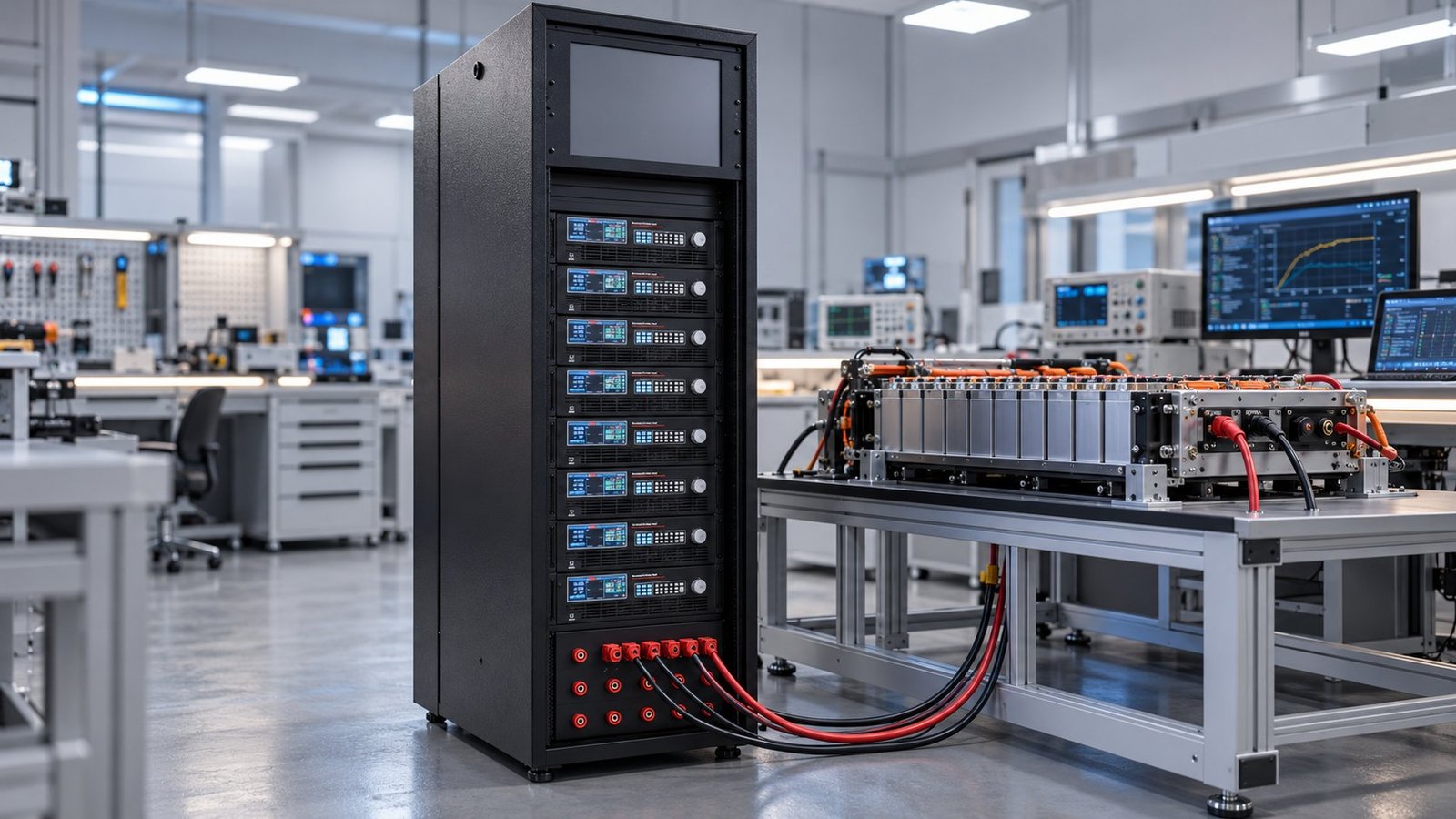
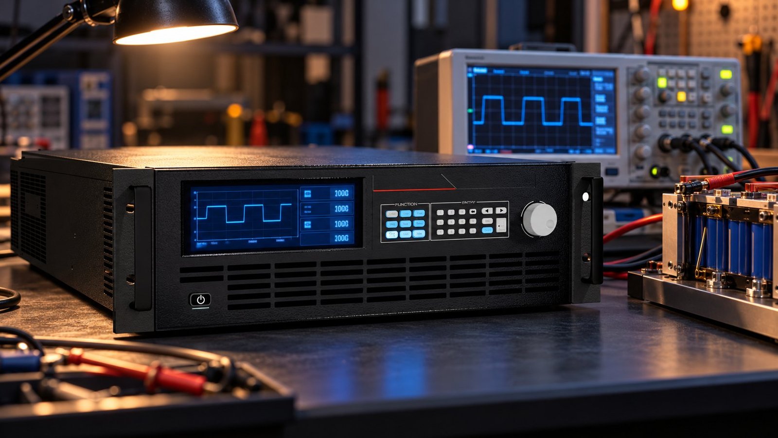
Choose the UltraPower class from the agreed maximum test voltage, then confirm headroom for the 5-second ramp. The EV & Battery Pack Test Power Supply range maps the bench to six bidirectional and regenerative DC supply classes.
| Voltage class | Use when | Decision check |
|---|---|---|
| 360 V | The REESS maximum voltage remains within the 360 V class | Confirm voltage headroom at the overcurrent level |
| 500 V | The test requires a higher-voltage pack profile | Check the agreed maximum voltage against the class limit |
| 750 V | The REESS operates in the 750 V range | Verify current stability through the full 5-second ramp |
| 1000 V | The pack or subsystem requires a 1000 V source class | Confirm insulation, measurement and protection interfaces |
| 1500 V | The test setup needs a 1500 V class | Review cabinet integration and trip isolation before testing |
| 2250 V | The agreed maximum voltage requires the 2250 V class | Approve the complete high-voltage risk assessment first |
Across the range, bidirectional operation supports both charge and discharge power flow. The specified response is ≤5 ms, accuracy is 0.02% F.S., and current-limit behaviour must be selected and logged before the run. Use the High Voltage DC Power Supply Selection Guide when the voltage class, cabinet layout and regenerative path need a single review.
See also: battery pack test power supply
What changes with GRSP/2026/25?
GRSP/2026/25 is an October 2026 proposal to delete Annex 9J and treat it as reserved. It is scheduled for formal review in December, but it is not yet law and does not replace the effective 2026 text.
Keep UN Regulation No 100 – 2026/1695 as the active baseline in your procedure. Add GRSP/2026/25 as a monitored change item with its date, source and review status. Do not relabel a completed test as exempt or reserved until the regulatory text is formally adopted and your approval authority has updated the method.
- Freeze the current Annex 9J conditions, ramp profile and evidence fields under a controlled document revision.
- Add a change note stating that GRSP/2026/25 proposes reserved status and remains under review.
- Keep the 5-second measured-current trace, overshoot value and trip trigger available for later comparison.
- Require engineering approval before changing the voltage class, current-limit behaviour or protection threshold.
UN R100 overcurrent test: practical FAQ
Is GRSP/2026/25 already in force?
No. GRSP/2026/25 is a proposal dated 14 October 2026 and scheduled for formal review in December. Use the effective UN Regulation No 100 – 2026/1695 text until an adopted change applies.
Does the Annex 4 equalisation check replace Annex 9J?
No. The Annex 4 paragraph 2.1 calculation is a separate resistance check using at least 0.2 A and R = U/I. It does not demonstrate the 5-second overcurrent ramp or protection-trip response.
What result should a lab report include?
Include the source voltage, starting SOC, ambient temperature, current setpoint, actual current overshoot, 5-second trace, protection-trip trigger and temperature-stabilisation evidence.
What should you change on your test bench now?
Lock the current Annex 9J method to the August 2026 effective text, then add an October proposal watch item to your change register. Ashkan, power supply engineer, recommends specifying the source class, measured-current logging and trip evidence before approving the next EV battery overcurrent test. Choose a bidirectional direct current power source that matches your voltage class and regenerative path →