A battery simulator for BMS testing reproduces repeatable cell or pack electrical conditions so you can verify thresholds, balancing, diagnostics and protection responses. After GB/T 47136-2026 entered force on 1 May 2026, select the architecture by cell count and fault coverage, then prove pack behaviour with measured voltage, current and trip-timing data.
The gap in many selection guides is the boundary between cell-level coverage and high-voltage pack validation. This workflow maps the SOH and state-of-safety indicators in GB/T 47136-2026 to simulator inputs, data collection and acceptance tests. It is written by Ashkan, power supply engineer at Ultra Power Systems.
What changed for BMS testing after 1 May 2026?
GB/T 47136-2026 changes the acceptance question from whether a source can set voltage to whether your bench can reproduce and evidence the inputs behind battery-health and safety decisions. The GB/T 47136-2026 Official Record lists the standard; use its requirements as a traceability layer over your electrical test matrix, not as a reason to combine cell and pack testing into one instrument.
What does clause 6.1.2 mean for test data?
Clause 6.1.2 gives a 0.1 Hz minimum data-collection reference — one sample every 10 seconds — and points to GB/T 38661-2020 clauses 5.4.2–5.4.4 and 5.5. Treat 0.1 Hz as a record-rate floor. Protection trips, current steps and fault transitions still need faster acquisition and timestamped event capture.
See also: iso 15118-23
How do SOH and safety indicators map to a simulator?
GB/T 47136-2026 clause 5.1 covers SOH indicators, while clause 5.2 covers state-of-safety indicators. A simulator can drive the electrical conditions that feed these decisions, but it cannot prove every physical cause behind them. Map each indicator to a controlled input, an observed BMS output and a stated coverage limit.
| Indicator or decision | Simulator evidence | Coverage boundary | Use when |
|---|---|---|---|
| SOH-related decision | SoC and OCV trajectories, pack voltage, current direction and repeatable load profiles | Does not reproduce cell ageing, capacity fade or thermal history by itself | Validating estimation logic and repeatable electrical inputs |
| State-of-safety decision | Overvoltage, undervoltage, current-limit, contactor and recovery sequences | Does not replace insulation, thermal, mechanical or abuse testing | Checking BMS thresholds, latching and recovery behaviour |
| Cell-level diagnostic | Independent cell voltage, imbalance, open-wire, short and reverse-polarity states | Requires isolated channels and fault switching | Testing AFE and per-cell wiring logic |
| Pack-level decision | High-voltage bus profiles, SoC/OCV models, source and regenerative sink operation | Does not expose individual cell faults unless separate cell emulation is connected | Validating pack controllers and power-stage interaction |
For battery emulator BMS validation, record the programmed condition, measured output, BMS decision, CAN message and trip timestamp. A pack simulator can validate aggregate high-voltage logic. It cannot substitute for a multi-channel cell simulator when the requirement is per-cell imbalance, balancing-current measurement or open-wire coverage.
Which architecture fits cell and pack validation?
Choose a multi-channel cell simulator for individual cell measurements and wiring faults. Choose pack-level battery emulation for high-voltage source, sink and model behaviour. The two architectures overlap in BMS validation, but they do not provide the same fault granularity.
| Example | Concrete capability | Best use | Decision limit |
|---|---|---|---|
| ET System N9000 | 36 channels, 0.5 mV voltage accuracy, response of ≤1 ms, plus open-wire, short and reverse-polarity faults | Cell-level AFE, imbalance, balancing and wiring diagnostics | Not a replacement for a 1000 V pack source and regenerative sink |
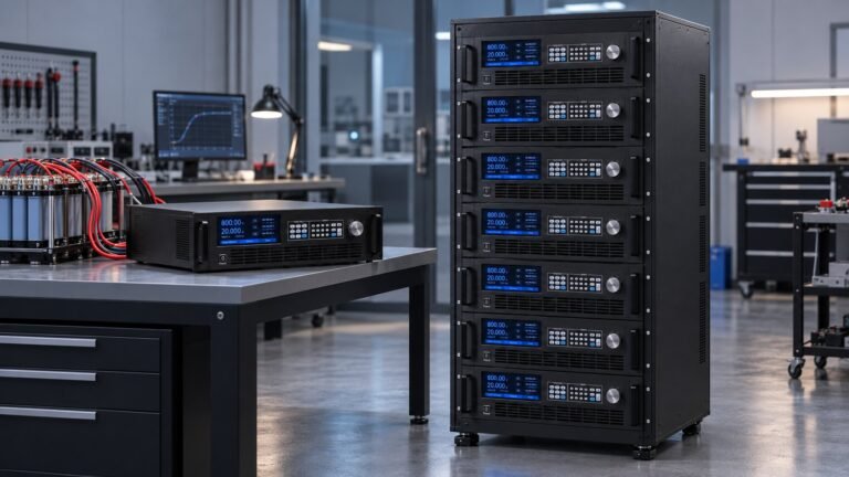
| Ultra N35500 | 360 V, 500 V, 750 V, 1000 V, 1500 V and 2250 V classes; seven model libraries plus custom curves; SoC/OCV control; regenerative source and sink | Pack-level voltage, current, charge, discharge and model-driven BMS decisions | Does not replace independent cell channels for per-cell fault coverage |
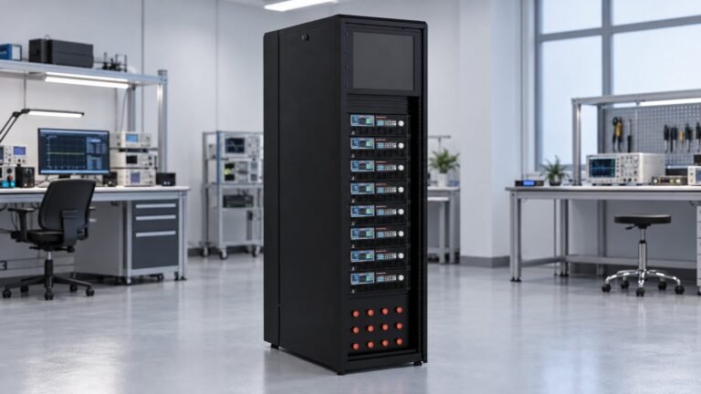
| Combined bench | Cell channels paired with a high-voltage bidirectional DC supply | Full validation from AFE faults to pack-controller decisions | Requires coordinated safety, timing, calibration and data logging |
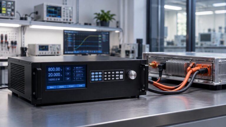
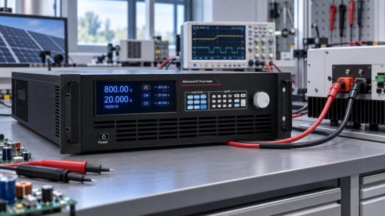
A concrete Ultra example is the N35542-1000-80 — 1000 V, ±80 A and 42 kW. The N35500 platform also supports bidirectional operation and up to 93% regenerative efficiency. For model-driven work, review the NS81000 battery simulation software overview and confirm the required curve format, control interface and data export.
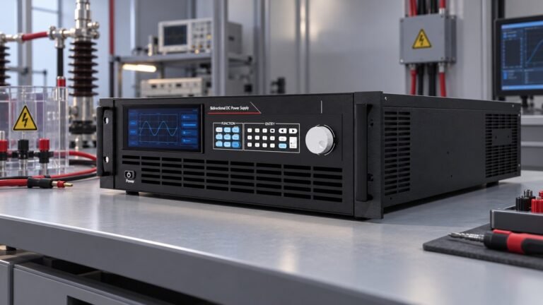
Use Ultra’s bidirectional and regenerative DC power supply range for pack-level source and sink requirements. Keep a separate multi-channel cell simulator wherever the test case includes battery cell fault simulation, per-cell balancing or individual open-wire diagnosis.
See also: EN50530 & Sandia: PV Inverter MPPT Test Standards
What should you specify and measure before buying?
Qingdu’s 31 August 2026 buyer guide provides a practical selection frame: cell count, isolated channels, current sinking, accuracy, dynamic response, fault coverage, automation, calibration and service. Convert those topics into purchase gates with a named failure mode for each gate.
- Cell count and architecture — failure mode: a 4S prototype passes, but a 12S or 24S fixture cannot be wired without replacing the simulator.
- Isolation and common-mode voltage — failure mode: series-connected channels create measurement error, output damage or an unsafe floating condition.
- Source and sink current — failure mode: balancing current raises the cell voltage because the output cannot absorb current at the required operating voltage.
- Accuracy and resolution — failure mode: an overvoltage threshold appears to pass because display resolution is mistaken for output accuracy.
- Dynamic response and sampling — failure mode: a protection event is missed because a 0.1 Hz log records the state but not the transition.
- Automation and interfaces — failure mode: CAN, LAN or SCPI timing cannot correlate the simulator event with the BMS message and contactor output.
- Factory acceptance measurement — require an Ultra result on the N35542-1000-80 for a 0–80 A step, including measured voltage droop in volts and settling time in milliseconds. Also require trip latency in milliseconds for one overvoltage, open-wire or balancing-current-limit trigger. A catalogue response figure is not a measured trace.
- Calibration and service — failure mode: an audit finds no uncertainty, traceability, calibration interval, spare-module plan or repair turnaround.
FAQ: battery simulator selection for BMS teams
Can a pack-level simulator replace a 36-channel cell simulator?
No. Pack-level battery emulation covers aggregate voltage, current, SoC, OCV and source-sink behaviour. A 36-channel system such as the ET System N9000 is better suited to individual cell imbalance, open-wire, short and reverse-polarity testing.
Does the 0.1 Hz guidance prove transient protection?
No. The 0.1 Hz minimum supports periodic data collection. Use a faster measurement path for a 0–80 A step, voltage droop, settling time and trip latency, then store the event trace with the slower compliance record.
Is the N35542-1000-80 suitable for every 1000 V pack?
Only if the pack test stays within 1000 V, ±80 A and 42 kW, including transients and regenerative energy. Confirm voltage margin, current duration, load profile, protection timing and thermal derating before acceptance.
What is the practical choice for your test bench?
Use isolated cell channels for per-cell BMS faults and pack-level battery emulation for high-voltage operating decisions. Keep both layers when your safety case covers both. Review Ultra’s battery simulator DC power supply range for pack-level BMS validation, then send your cell count, voltage class, current, fault cases and required measured traces for configuration →