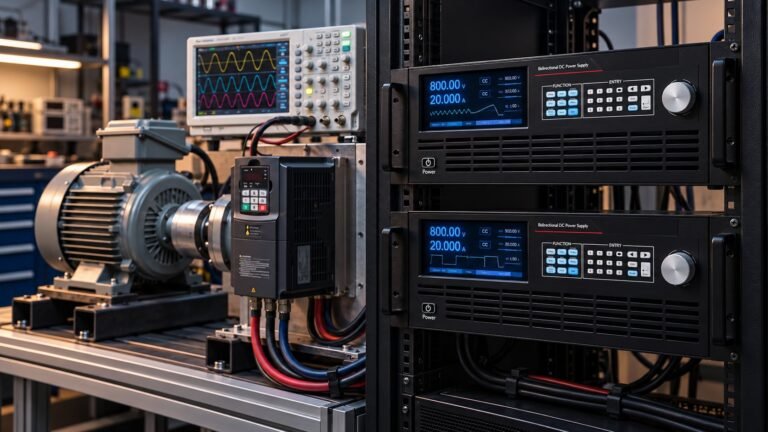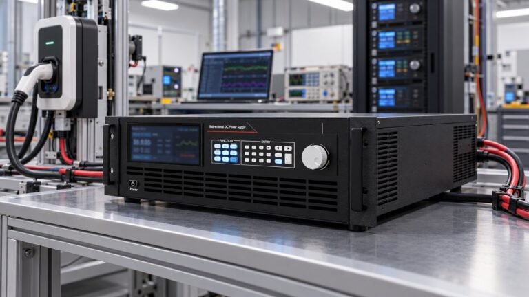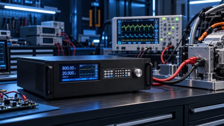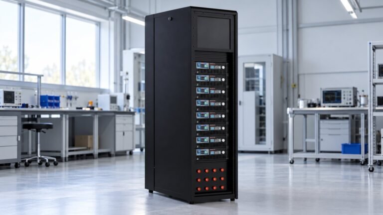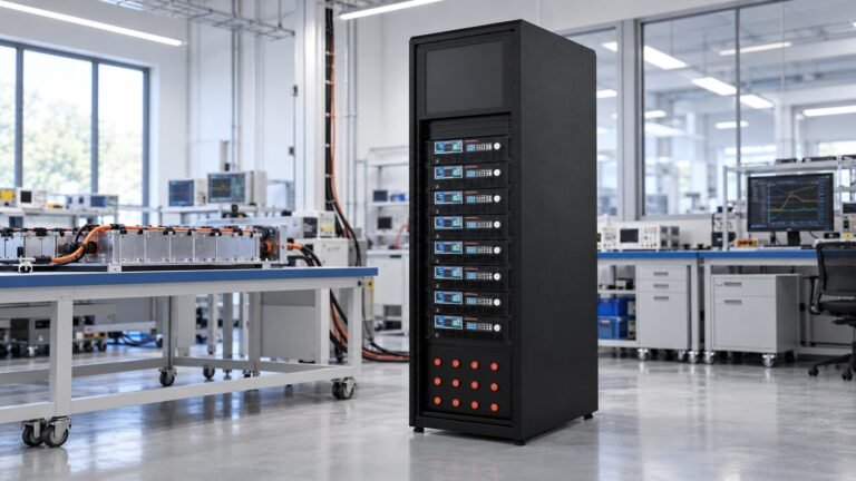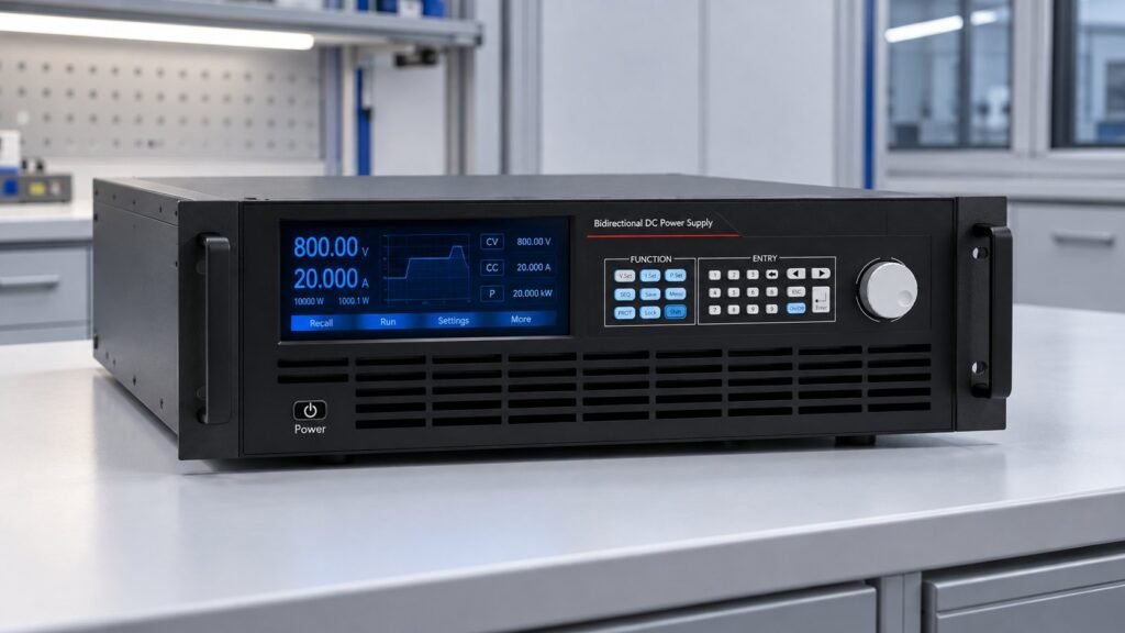
A compliant GB 38031-2025 test setup must prove more than a pack result. After 1 July 2026, your bidirectional bench needs traceable voltage and current measurement within ±0.5% FS, process error within ±1%, data intervals no longer than 15 seconds, correct preconditioning, and controlled 20–80% cycling before the 300-cycle short-circuit sequence.
The procurement question is whether your source, sink, sensors, protection logic and data record can defend each test step. I am Ashkan, power supply engineer at Ultra Power Systems. This guide turns the standard into an acceptance checklist for 360 V to 2250 V bidirectional and regenerative DC systems.
What must a GB 38031-2025 test setup prove?
Your GB 38031-2025 test setup must demonstrate measurement accuracy, executed-process accuracy and time resolution before it produces evidence for a battery pack safety test. Sections 6.2–6.4 are the procurement core because every later test depends on the recorded electrical conditions.
The National Standard Information Public Service Platform records GB 38031-2025 as published on 28 March 2025 and implemented on 1 July 2026. The GB 38031-2025 English PDF provides the clause structure used here. Battery Design’s GB 38031-2025 “no fire, no explosion” overview covers the wider pack tests; this article focuses on the bench that produces defensible evidence.
| Requirement | Acceptance evidence | Use when |
|---|---|---|
| Voltage and current measurement | ±0.5% FS or better, with calibration traceability | Accepting the measurement chain before pack testing |
| Process error | Executed voltage, current and timing profile within ±1% | Verifying that commanded tests match actual pack conditions |
| Data interval | No interval longer than 15 seconds | Proving SOC transitions, protection events and test duration |
| Insulation | At least 100 Ω/V, or 500 Ω/V where an AC circuit exists | Checking the pack and connected test circuit before energisation |
| Over-current response | Current reaches the defined over-current level within 5 seconds | Validating Section 8.2.12 response timing |
How should you specify the measurement chain?
Specify the DC source, regenerative sink, sensors, remote-sense wiring and logger as one measurement chain. A nameplate voltage or power rating is not enough. Your acceptance document should state full-scale ranges, calibration points, sample interval, cable losses, sense location and the response to an out-of-tolerance record.
Where should remote sense and logging sit?
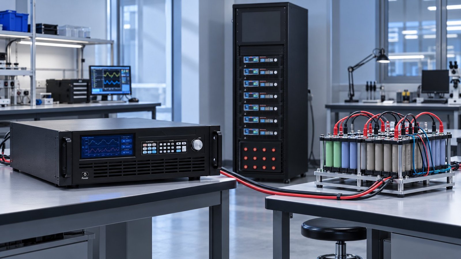
Place remote-sense conductors at the battery-side busbars or pack terminals, not at the supply output studs. Run positive and negative power cables as a matched pair, separate the sense pair from high-current conductors, and record the logger clock against the source controller. For voltage-class selection across 360 V, 750 V, 1000 V, 1500 V and 2250 V, use the High Voltage DC Power Supply Selection Guide.
- Use voltage and current channels whose full-scale accuracy is no worse than ±0.5%.
- Record pack voltage, source current, sink current, SOC, contactor state, insulation status and protection state.
- Set the acquisition interval to 10 seconds or less, leaving margin below the 15-second limit.
- Keep cable resistance and remote-sense drop in the acceptance record.
- Use a defined abort state for insulation failure, current-limit entry or missing samples.
See also: lv123 standard
How does the bench run fast-charge-cycle safety?
For Section 8.1.8 fast-charge-cycle safety, the bench charges the pack from 20% to 80% SOC in no more than 15 minutes, repeats that cycle 300 times, then supports the external-short-circuit test. The source controls the charge profile; the sink absorbs discharge and regenerative energy without interrupting the logged sequence.
How are charge, discharge and reversal controlled?
During charge, the bidirectional converter sources controlled DC current into the pack. During discharge, it reverses power flow and operates as a regenerative load. At current reversal, the controller passes through zero with a defined slew rate rather than allowing an uncontrolled polarity step. A dedicated regenerative dc electronic load is useful when the test requires sustained discharge power and energy recovery.
Where does regenerative energy go?
The sink returns discharge energy to the AC system through the bidirectional power stage, subject to the site’s regeneration limits. Confirm the AC interface, protective isolation and energy-flow interlocks before the pack test. The neighbouring ac dc regenerative converter commissioning guide covers the related AC-side checks.
- Run Section 7.2.2 preconditioning and verify the required starting SOC. Failure trigger: the pack does not reach the defined state; response: hold the sequence and record the conditioning result.
- Start the 20–80% SOC charge profile and verify completion within 15 minutes. Failure trigger: the transition exceeds 15 minutes; response: stop the cycle count and flag the profile as failed.
- Repeat the fast-charge cycle 300 times while logging voltage, current, SOC and protection state. Failure trigger: a sample gap exceeds 15 seconds or process error exceeds ±1%; response: quarantine the run and preserve the raw log.
- Transfer the conditioned pack to the external-short-circuit sequence. Failure trigger: insulation falls below 100 Ω/V, or below 500 Ω/V where an AC circuit exists; response: open the contactor, block source and sink operation, and record the insulation fault.
See also: direct current power source
What does a 750 V acceptance record look like?
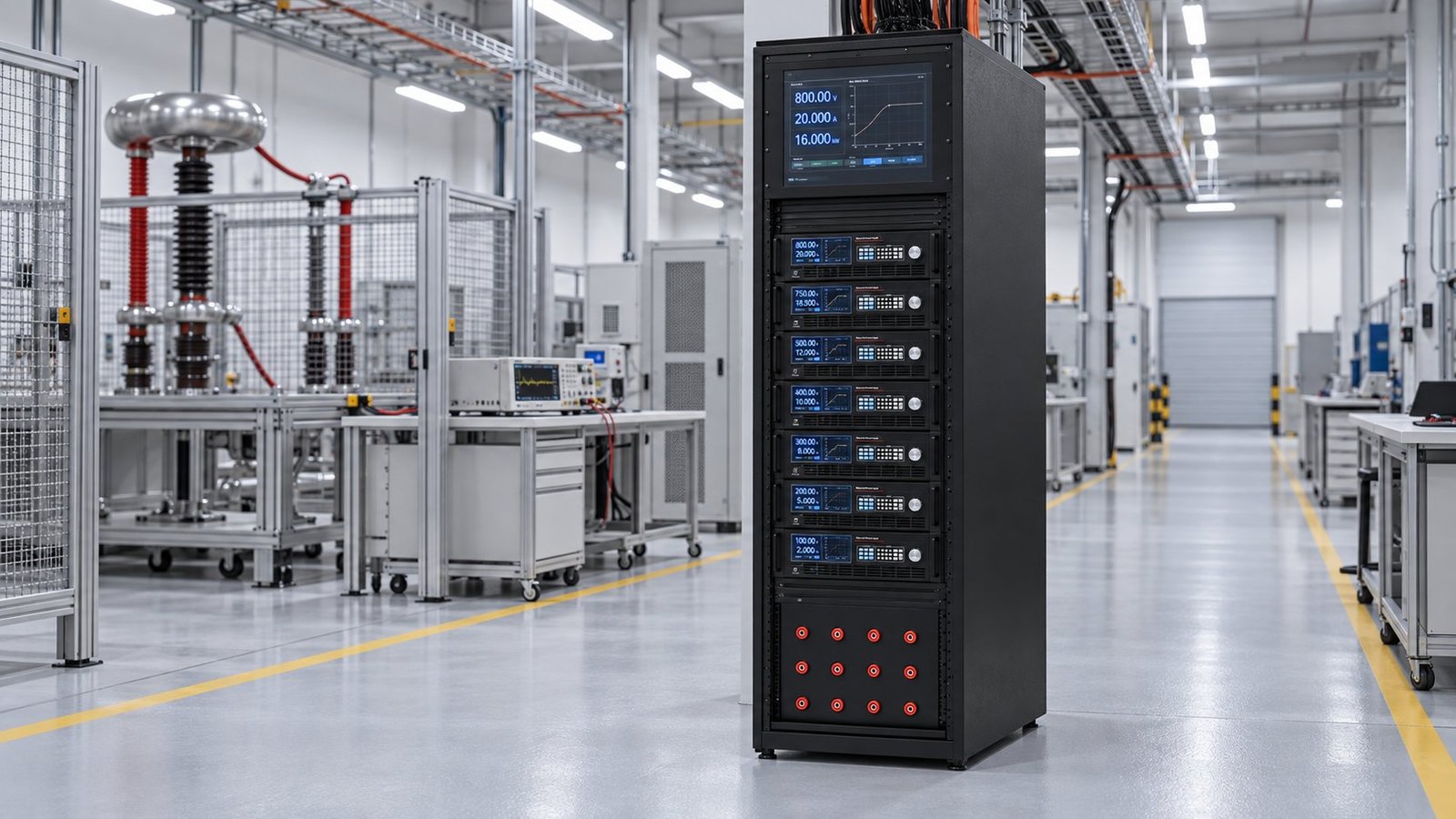
A configured 750 V class should show the cable arrangement, sense point, logger interval and measured error on the acceptance sheet. In one Ultra Power Systems configuration, the positive and negative output cables run as a matched pair to the pack busbars, while the remote-sense pair terminates at those same busbars. The logger records every 10 seconds.
At a 750.00 V and 100.00 A command, the recorded values were 748.65 V and 99.70 A. That is −1.35 V, or −0.18% FS, and −0.30 A, or −0.30% FS. Both results sit inside the ±0.5% FS measurement limit. The associated process-error result was 0.62%, inside the ±1% requirement.
For a 750 V pack, the insulation floor is 75,000 Ω under the 100 Ω/V rule. Where an AC circuit exists, the 500 Ω/V rule becomes 375,000 Ω. The failure response must be deterministic: insulation failure opens the contactor, an over-current condition enters current limit, and an out-of-tolerance log invalidates the affected step.
GB 38031-2025 test setup FAQ
Is ±0.5% FS the same as ±0.5% of the reading?
No. ±0.5% FS is referenced to the selected full-scale range. Select ranges carefully so the required pack voltage and current are measured with useful resolution.
Why does the 15-second interval matter?
The interval limits how much test history can be missing. A 10-second setting gives practical margin for showing SOC movement, protection activation and the timing of current changes.
What must happen before the short-circuit test?
Complete the 300 fast-charge cycles from 20% to 80% SOC, verify the logged results, confirm insulation status and transfer the conditioned pack under a controlled protection state.
What should you specify before purchase?
Specify the GB 38031-2025 test requirements as measurable bench functions: ±0.5% FS sensing, ±1% process error, ≤15-second logging, 7.2.2 preconditioning, 8.1.8 fast-charge cycling, insulation thresholds and the 8.2.12 five-second over-current response. For a configured direct current power supply covering 360 V to 2250 V classes, review the direct current power supplies available for your pack voltage, current and regenerative-energy path →